


The outdoor-air damper closes. The control allows 90 sec-
onds for the damper to close in case it is in the full open
position. Next, the indoor-fan contactor will energize. The
outdoor-air damper will remain at 0% for 30 seconds. It will
then move to the 10% position for another 30 seconds. This
will be repeated at every 10% increment for 30 seconds until
the damper reaches 100% open. Close DIP switch no. 4 dur-
ing the 30 seconds immediately after the desired outdoor air
minimum damper position. The 30-second time period is to
allow time where DIP switch no. 4 can be closed. The de-
fault value of the minimum outdoor air damper position is
20%. If the desired minimum position is 30%, allows the
damper position to go to 10% for 30 seconds, then 20% for
30 seconds, and when it reaches 30% close DIP switch
no. 4 during the 30-second period following the 30%
position.
The minimum outdoor air damper position isnow set. Close
DIP switch no. 6.
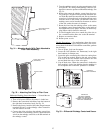
ECONOMIZER SETTINGS
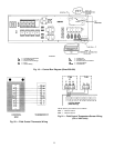
Accessory Enthalpy Control (Fig. 33) — The control
(HH57AC077) is mounted in the economizer hood. See
Fig. 24. The enthalpy setting adjustment is on the enthalpy
control. For maximum benefit of outdoor air, set enthalpy
control to A. See Fig. 34 and 35.
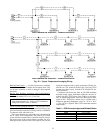
Enthalpy Control Installation — The outdoorair enthalpy con-
trol is installed on the inside panel of the outdoor air hood.
The enthalpy control should be mounted when the outdoor
air hoods are assembled. To install the control, perform the
following procedure:
1. Turn off all power. Ensure disconnect is locked out.
2. Remove the economizer inlet filters from the bottom of
the right hand economizer hood. See Fig. 24. See Fig. 36
for economizer details.
3. Mount the outdoor air enthalpy sensorinside theright econo-
mizer hood on the right side panel of the hood, adjacent
to the outdoor-air thermistor.
4. Locate the red, violet, and brown wires near the outdoor
air thermistor. Remove the splice from the red and violet
wires. Remove the cap from the brown wire.
5. Install a
1
⁄
4
-in. push on terminal (field-supplied) on the
violet and brown wires.
6. Connect a
1
⁄
4
-in. push on terminal (field provided) to one
end of a 18-gage, 6-in. jumper wire (field-provided). Con-
nect the other end to the red wire and attach a
1
⁄
4
-in. push
on connector (field provided).
7. Connect the red wire with the jumper to terminal TR1.
Connect the jumper to terminal 2. Connect the brown wire
to terminal TR. Connect the violet wire to terminal 3. All
connections are on the enthalpy control.
8. Replace the economizer filters.
9. Return power to unit.
Accessory Differential Enthalpy Control (Fig. 33) — The
control (HH57AC077), in conjunction with the accessory en-
thalpy sensor (HH57AC078), controls economizer opera-
tion according to the differential enthalpy. The control is
mounted in the economizer hood. The sensor is mounted in
the return duct (48EJ/EK) or return air plenum (48EW/EY).
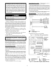
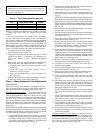
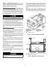
HOOD SIDE
(SLOTTED)
HOOD
TOP
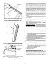
Fig. 28 — Adding Foam Strip to Hood Side
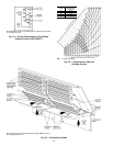
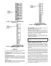
BLOCKOFF BAFFLE
GRAY FOAM STRIP
Fig. 29 — Adding Foam Strip to Blockoff Baffle
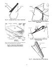
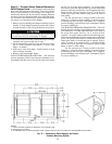
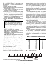
MOUNTING ANGLE
(WITHOUT TABS)
FILTER TRACK
ASSEMBLY
Fig. 30 — Mounting Angle (Without Tabs) Attached
to Filter Track Assembly
26