


• When the outdoor air quality is greater than the outdoor
air quality set point (ppm)
High priority — When the priority is set to high, the IAQ
set point controls the outside air damper exclusively, with
no regard to comfort conditioning.
TIME GUARD CIRCUIT— The Time Guard function (built
into the rooftop control board) maintains a minimum off time
of 5 minutes, a minimum on time of 10 seconds, and a
10-second delay between compressor starts.
CRANKCASE HEATER — Unit main power supply must
remain on to provide crankcase heater operation. The crank-
case heater in each compressor keeps oil free of refrigerant
while compressor is off.
HEAD PRESSURE CONTROL — Each unit has a fan cy-
cling, outdoor thermostat to shut off the outdoor-fan mo-
tor(s) at 55 F (one outdoor-fan motor on 024-034 units and
two outdoor fan motors on 038-048 units). The head pres-
sure control permits unit to operate with correct condensing
temperatures down to 35 F outdoor-air temperature.
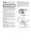
MOTORMASTER III CONTROL — The Motormaster
III Solid-State Head Pressure Control is a field-installed ac-
cessory fan speed control device actuated by a temperature
sensor. It is specifically designed for use on Carrier equip-
ment and controls the condenser-fan motor speed in re-
sponse to the saturated condensing temperature. For outdoor
temperatures down to −20 F, it maintains condensing tem-
perature at 100 F. Refer to the accessory Motormaster in-
stallation instructions for more information.
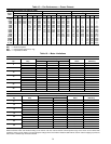
CAPACITY CONTROL, COOLING — The cooling capac-
ity staging tables are shown in Tables 20 and 21.
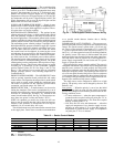
Table 20 — Cooling Capacity Staging Table, CV Units
with 2 Compressors
Stages
0
1
Economizer
23
Compressor 1 off off on on
Compressor 2 off off off on
NOTE: OnCV units thatrequire additionalunloading, add suctionpres-
sure unloaders to Compressor 1 only.
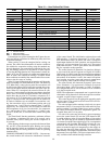
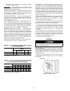
Table 21 —Cooling Capacity Staging Table VAV Units
with 2 Compressors and 2 Unloaders*
Stages
0123456
Compressor 1 offonononononon
Unloader 1 off on on off on on off
Unloader 2 off on off off on off off
Compressor 2 off off off off on on on
*40 ton units have only one unloader.
FIELD TEST — The field test program is initiated by mov-
ing up DIP switch no. 4 to the OPEN position. The outdoor-
air damper will close. The control allows 90 seconds for the
damper to close in case it was in the full open position. Next,
the indoor-fan contactor will be energized, and the outside-
air damper will begin to open to its default value of 20% and
stay at that position for a short period of time. The outdoor-
air damper will then open to its full open position and stay
at that position for a short period of time. The outdoor-air
damper will then close.
If the unit is equipped with power exhaust, stage 1 will be
energized for 5 seconds. If the unit is configured for stage 2
of power exhaust, stage 2 will be energized for 5 seconds
after the first stage is deenergized.
The first stage of heat will be energized for 30 seconds,
after which the second stage heat will be energized for an
additional 30 seconds. Heat is then deenergized.
The last step is the Cooling mode. Outdoor-fan contactor
no. 1 is energized. This is followed by each stage of cooling
energized with a 10-second delay between stages. After this
is complete, outdoor-fan contactor no. 2 is energized for
10 seconds.
The compressors will now deenergize, followed by the
outdoor-fan contactors and indoor-fan contactors. If the unit
is equipped with the Integrated Gas Control (IGC) board,
the indoor fan will continue to operate for an additional
30 seconds after deenergizing the circuit.
The field test is then complete.
SERVICE
Before performing service or maintenance operations on
unit, turn off main power switch to unit. Electrical shock
could cause personal injury.
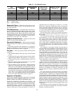
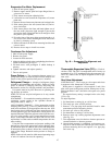
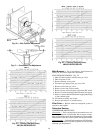
Service Access — All unit components can be reached
through clearly labelled hinged access doors. These doors
are not equipped with tiebacks, so if heavy duty servicing is
needed, either remove them or prop them open to prevent
accidental closure.
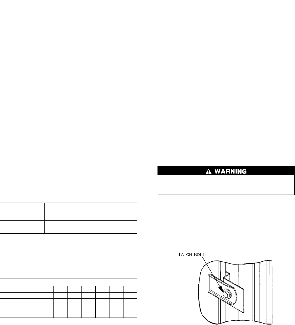
Each door is held closed with 3 latches. The latches are
secured to the unit with a single
1
⁄
4
-in.-20x
1
⁄
2
-in. long bolt.
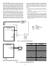
See Fig. 45.
Fig. 45 — Door Latch
44