


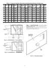
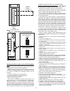
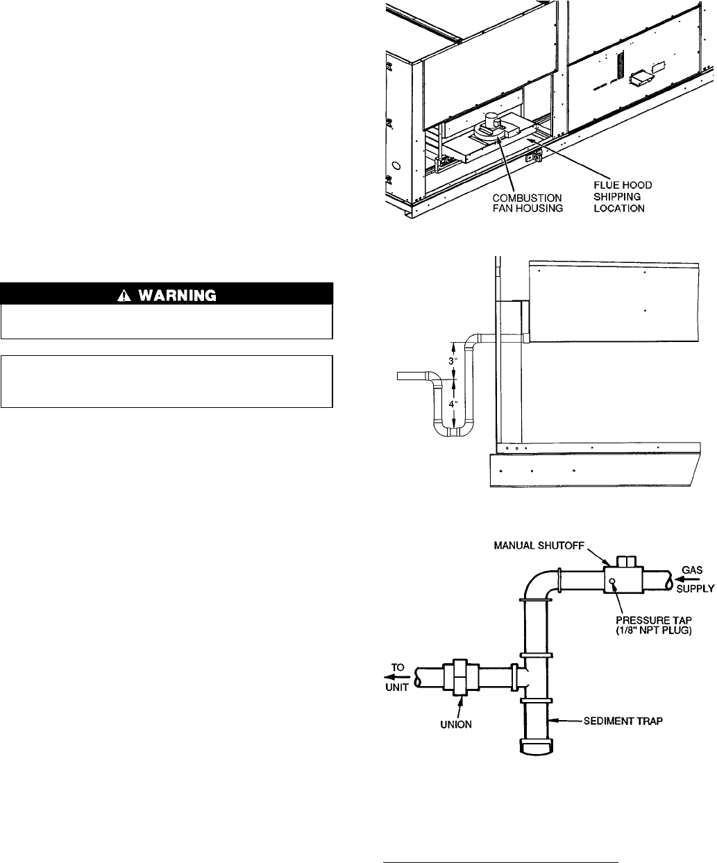
Step5—TrapCondensate Drain — See Fig. 3-6
for drain location. Condensate drain is open to atmosphere
and must be trapped. Install a trapped drain at the drain lo-
cation. A trap at least 4-in. deep must be used. See Fig. 12.
Trap must be installed to prevent freeze-up.
Condensate pans are sloped so that water will completely
drain from the condensate pan to comply with indoor air qual-
ity guidelines. The condensate drain pan is fitted with a 1-in.
FPT coupling.
Step 6 — Install Gas Piping — Unit is equipped for
use with natural gas. Installation must conform with local
building codes or, in the absence of local codes, with the
National Fuel Gas Code, ANSI Z223.1.
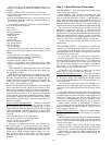
Install manual gas shutoff valve with a
1
⁄
8
-in. NPT pres-
sure tap for test gage connection at unit. Field gas piping
must include sediment trap and union. See Fig. 13. An
1
⁄
8
-in. NPT is also located on the gas manifold adjacent to
the gas valve.
Do not pressure test gas supply while connected to unit.
Always disconnect union before servicing.
IMPORTANT: Natural gas pressure at unit gas con-
nection must not be less than 5 in. wg or greater than
13.5 in. wg.
Size gas-supply piping for 0.5-in. wg maximum pressure
drop. Do not use supply pipe smaller than unit gas
connection.
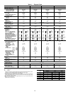
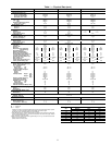
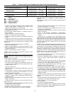
Step 7 — Controls Options — The control options
that the units can provide are based on the following param-
eters: CV (constant volume) or VAV (variable air volume)
operation; stand-alone unit with field-supplied sensors in-
stalled (CV or VAV); as a system via Carrier Comfort Sys-
tem (TEMP or VVT); optional electronic expansion board
installed (CV or VAV); linked to the Carrier Comfort
Network; and availability of a computer and software
(ComfortWorks™ Building Supervisor, and Service Tool) or
LID-2B accessory installed to access the base control board.
See Table 3.
NOTE: Access to the base control board allows unit occu-
pancy schedules, unit timeclock, and various set points to be
changed from their factory-defined default settings.
All units are equipped with a supply air thermistor (SAT)
located in the supply fan discharge and an outdoor air ther-
mistor (OAT) located in the outdoor air hood. Variable air
volume units are supplied with a return air thermistor (RAT)
located on the return air damper support.
CONSTANT VOLUME APPLICATIONS — The units, as
shipped, are operable as stand-alone units, usingeither a stand-
ard (mechanical or electronic) 2-stage heat, 2-stage cool ther-
mostat, or with an electronic room sensor and a timeclock to
establish unit start and stop times.
With a standard thermostat (programmable is optional),
heating and cooling operation is set by space temperature.
With a space sensor and timeclock, the machine will op-
erate at default values unless they are changed using appro-
priate input devices. The space sensor senses space tempera-
ture and may be equipped with a timed override feature, which
allows unit operation during unoccupied periods.
The space sensors may be used in multiples of 4 or 9 to
achieve space temperature averaging. The use of a space sen-
sor also allows the unit to be turned on and off from a re-
mote signal.
Features with Thermostat Control of Unit
• two-stage heating
• two-stage cooling
• control of unit using Y1, Y2, W1, W2, and G thermostat
inputs
• control of the indoor fan
• outdoor-air temperature/supply-air temperature
monitoring
• control of an outdoor air condenser fan based on outdoor-
air temperature
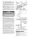
Fig. 11 — Combustion Fan Housing Location
Fig. 12 — Condensate Drain Trap Piping Details
(Typical Roof Curb or Slab Mount Shown)
Fig. 13 — Field Gas Piping
13