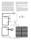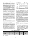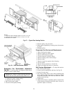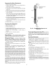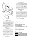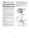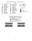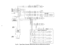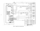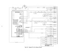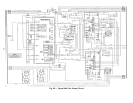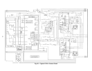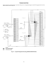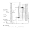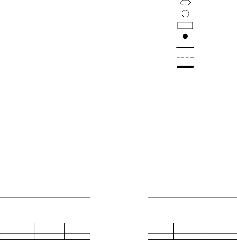
LEGEND and NOTES for Fig. 56-60 — Typical Wiring Schematics
AHA — Adjustable Heat Anticipator
BP — Building Pressure
BR — Burner Relay
C—Contactor, Compressor
CAP — Capacitor
CB — Circuit Breaker
CC — Cooling Compensator
CCB — Controller Circuit Breaker
CCH — Crankcase Heater
COM — Communication
COMP — Compressor Motor
CR — Control Relay
DM — Damper Motor
DP — Duct Pressure
EC — Enthalpy Control
EQUIP — Equipment
FLA — Full Load Amps
FPT — Freeze Protection Thermostat
FU — Fuse
GRD — Ground
GVR — Gas Valve Relay
HPS — High-Pressure Switch
HS — Hall Effect Sensor
HV — High Voltage
IDM — Induced-Draft Motor
IFC — Indoor Fan Contactor
IFCB — Indoor Fan Circuit Breaker
IFM — Indoor-Fan Motor
IFR — Indoor-Fan Relay
IGC — Integrated Gas Unit Controller
IP — Internal Protector
L—Light
LPS — Low-Pressure Switch
MGV — Main Gas Valve
NC — Normally Closed
NO — Normally Open
OAT — Outdoor-Air Thermistor
OFC — Outdoor-Fan Contactor
OFM — Outdoor-Fan Motor
PEC — Power Exhaust Contactor
PEM — Power Exhaust Motor
PES — Power Exhaust Sequencer
PESC — Power Exhaust Sequencer
Controller
PL — Plug Assembly
R—Relay
RAT — Return-Air Thermistor
RS — Rollout Switch
SAT — Supply-Air Thermistor
TB — Terminal Block
TC — Thermostat Cooling
TH — Thermostat Heating
TRAN — Transformer
UL — Compressor Unloader
VFD — Variable Frequency Drive
Terminal (Marked)
Terminal (Unmarked)
Terminal Block
Splice
Factory Wiring
Field Wiring
To Indicate Common Potential Only,
Not To Represent Wiring
NOTES:
1. Connect TRAN1 to H4 for 460 v units. Connect to H3 for 230 v. If
208/230 v units are run with a 208 v power supply connect to H2.
2. Connect TRAN2 to black lead for 460 v units. Connect to orange
lead for 230 v units. If 208/230 v units are run with a 208 v power
supply connect to red lead.
3. Circuit breaker musttrip amps are equal to or less than 156% FLA
for CB1 and CB2. All others are 140%.
4. If any of the original wire furnished must be replaced, it must be
replaced with type 90 C wire or its equivalent.
5. Compressors and/or fan motors are thermally protected.
6. Three phase motors are protected against primarysingle phasing
conditions.
7. Red wire and violet wire are spliced together at the factory. The
brown wire has a wire nut added at the factory.
TABLE A
THE FOLLOWING COMPRESSORS HAVE
TWO PARALLEL WIRES RUN FROM TB1
TO THE COMPRESSORS
(NOT SHOWN ON LABEL DIAGRAM)
COMPRESSOR
MODEL
VOLTAGE
WIRE
QUANTITY
06D-537 208/230-3-60 2
LEGEND
TABLE B
THEFOLLOWINGFANMOTORSHAVETWO
PARALLELWIRES RUNFROMTB1TOTHE
FAN MOTORS
(NOT SHOWN ON LABEL DIAGRAM)
INDOOR
MOTOR
VOLTAGE
WIRE
QUANTITY
20 HP 208/230-3-60 2
50


