


Remote Field Control — A switch closure across terminals
R and W1 on TB-3 will initiate the Occupied mode. This
can be done manually as well as through a field-supplied
timeclock.
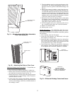
Service Tool, Building Supervisor, and ComfortWorks™
Software — Access to the control board can be achieved through
the terminal marked CCN via a 3-wire bus.
IMPORTANT: The default bus address is 0. The de-
fault element number is 1. Refer to CCN literature to
change the default values, if needed.
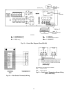
Carrier Comfort Network Interface — The 48E units can be
connected to the CCN. The communication bus wiring is sup-
plied and installed in the field. Wiring consists of shielded,
3-conductor cable with drain wire.
The system elements are connected to the communication
bus in a daisy chain arrangement. The positive pin of each
system element communication connector must be wired to
the positive pins of the system element on either side of it,
the negative pins must be wired to the negative pins, and the
signal pins must be wired to signal ground pins. Wiring con-
nections for CCN should be made at the 3-pin plug (CCN
located at the base board). Consult CCN literature for fur-
ther information.
Conductors and drain wire must be 20 AWG minimum
stranded, tinned copper. Individual conductors must be in-
sulated with PVC, PVC/nylon, vinyl, Teflon, or polyethyl-
ene. An aluminum/polyester 100% foil shield and an outer
jacket of PVC, PVC/nylon, chrome vinyl, or Teflon with a
minimum operating temperature range of −20 C to 60 C
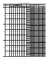
(−4 F to 140 F) is required. Table 5 lists cables that meet the
requirements.
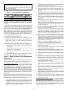
Table 5 — CCN Connection Approved Shielded Cables
MANUFACTURER CABLE PART NO.
Alpha 2413 or 5463
American A22503
Belden 8772
Columbia 02525
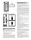
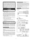
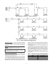
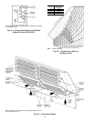
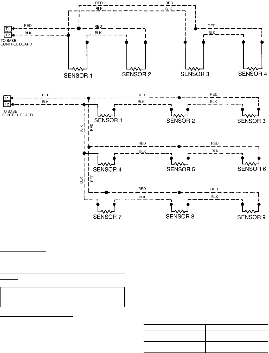
SPACE TEMPERATURE AVERAGING — 4 SENSOR APPLICATION
SPACE TEMPERATURE AVERAGING — 9 SENSOR APPLICATION
Fig. 22 — Space Temperature Averaging Wiring
23