


START-UP
Use the following information and Start-Up Checklist
on page CL-1 to check out unit PRIOR to start-up.
Unit Preparation — Check that unit has been installed
in accordance with these installation instructions and appli-
cable codes.
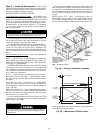
Compressor Mounting — Loosen the compressor hold-
down bolts until sidewise movement of the washer under
each holddown bolt head can be obtained. Do not loosen
completely as bolts are self-locking and will maintain
adjustment.
Service Valves — Ensure that the suction, discharge,
and liquid line service valves are open. Damage to the com-
pressor could result if they are left closed.
Internal Wiring — Check all electrical connections in
unit control boxes; tighten as required.
Refrigerant Service Ports — Each refrigerant sys-
tem has one suction port located in the top of the compressor
motor casing. All units also have one service port on the liq-
uid line valve and one on the compressor discharge valve.
Be sure that caps on the ports are tight.
Crankcase Heaters — Crankcase heaters are ener-
gized as long as there is power to the unit, except when the
compressors are operating.
IMPORTANT: Unit power must be on for 24 hours
prior to start-up. Otherwise, damage to compressor may
result.
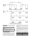
Variable Frequency Drive (VFD) — The variable
frequency drives arefactory set.These settingsinclude factory-
installed jumpers and software configurations. The only
field configured set point is duct static pressure. An Opera-
tion Manual is shippedwith eachVAV unit. This manual should
be used if the drive needs to be customized for a particular
application.
NOTE: The VFD will always provide the proper phase
sequence to the indoor-fan motor. The indoor-fan motor op-
erates in proper rotation regardless of the phase sequence to
the unit. If, upon start-up, the outdoor fans operate back-
wards but the indoor fan operates in the correct direction,
reverse any two leads to the main terminal block. All fans
will then operate in the correct direction.
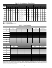
To set the duct static pressure, perform the following steps.
The factory setting is zero. The duct transducer has a range
from 0 to 5 in. wg. The transducer output is 4 to 20 mA,
therefore, 0 to 5 in. wg is proportional to the 4 to 20 mA and
must be expressed to the VFD in terms of percentage of the
frequency range. Refer to Table 7. The set point value is a
percentage of the maximum output frequency. Locate the duct
static pressure closest to that desired and use the correspond-
ing set point value. If necessary, interpolation between duct
static pressures is permissible.
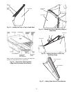
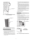
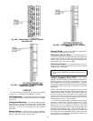
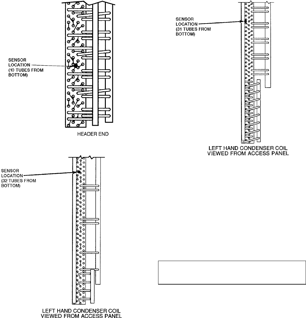
Fig. 40A — Motormaster III Sensor Location
(Sizes 024-034)
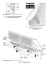
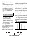
Fig. 40B — Motormasterா III Sensor Location
(Sizes 038 and 044)
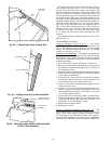
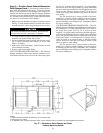
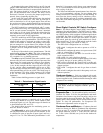
Fig. 40C — Motormaster III Sensor Location
(Size 048)
31