


Main Burners — For all applications, main burners are
factory set and should require no adjustment.
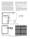
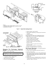
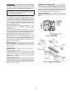
MAIN BURNER REMOVAL (Fig. 55)
1. Shut off (field-supplied) manual main gas valve.
2. Shut off power to unit.
3. Remove heating access panel.
4. Disconnect gas piping from gas valve inlet.
5. Remove wires from gas valve.
6. Remove wires from rollout switch.
7. Remove sensor wire and ignitor cable from IGC board.
8. Remove 2 screws securing manifold bracket to basepan.
9. Remove 4 screws that hold the burner support plate flange
to the vestibule plate.
10. Lift burner assembly out of unit.
11. Reverse procedure to re-install burners.
Filter Drier — Replace whenever refrigerant system is
exposed to atmosphere.
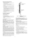
Protective Devices
COMPRESSOR PROTECTION
Overcurrent — Each compressor has one manual reset, cali-
brated trip, magnetic circuit breaker. Do not bypass connec-
tions or increase thesize ofthe circuitbreaker tocorrect trouble.
Determine the cause and correct it before resetting the breaker.
Overtemperature — Each 06D type compressor (024-038 units)
has an internal protector to protect it against excessively high
discharge gas temperatures.
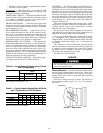
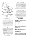
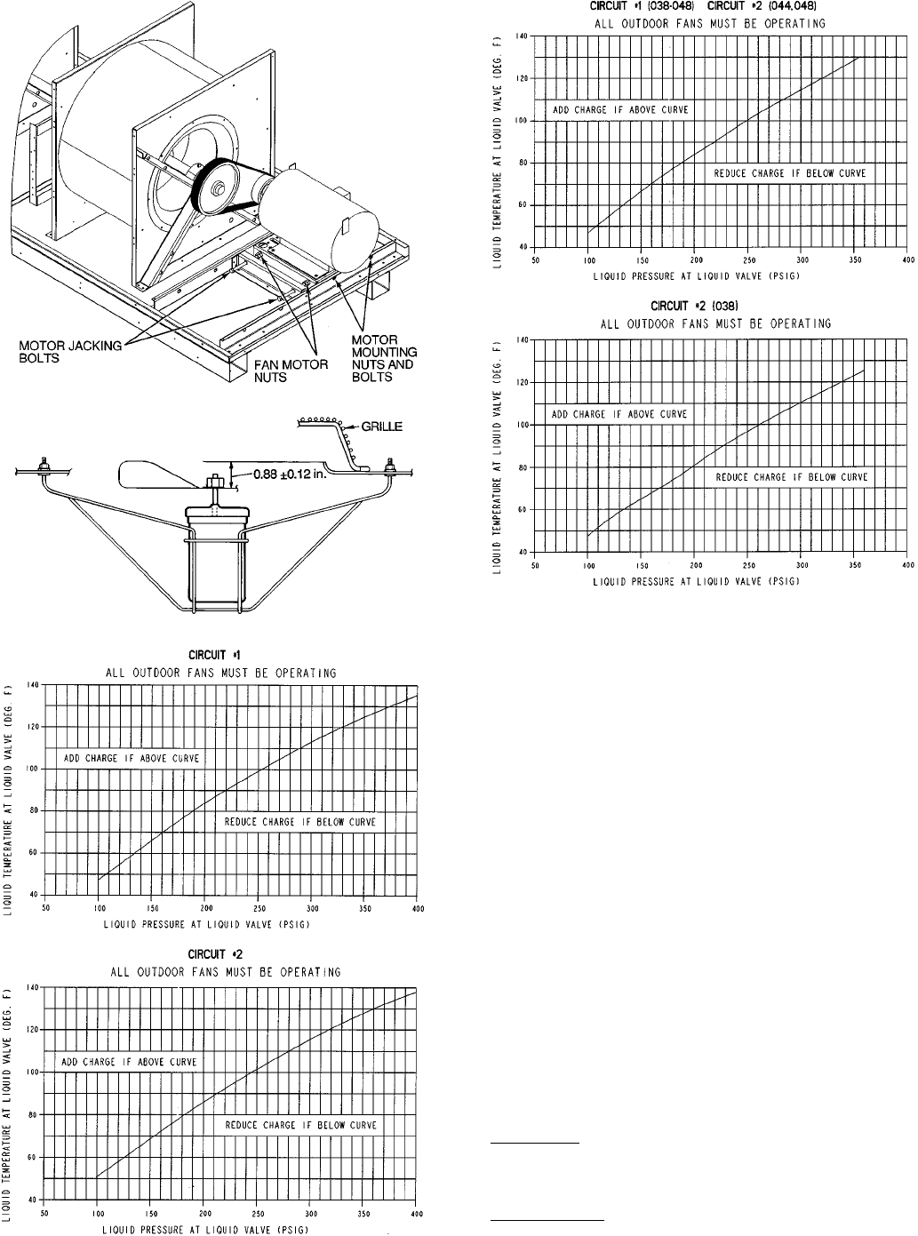
Fig. 50 — Belt Tension Adjustment
Fig. 51 — Condenser-Fan Adjustment
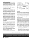
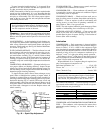
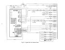
Fig. 52 — Cooling Charging Chart,
48EJ,EK,EW,EY024-034
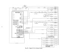
Fig. 53 — Cooling Charging Chart,
48EJ,EK,EW,EY038-048
48