


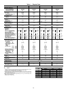
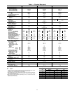
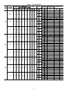
Table 1 — Physical Data (cont)
UNIT 48EJ,EK,EW,EY 038D/E 044D/E 048D/E
NOMINAL CAPACITY (tons) 35 40 45
OPERATING WEIGHT (lb)*
Unit
Al/Al† (Lo Heat/Hi Heat) 4442/4602 4668/4828 4955/5115
Al/Cu† (Lo Heat/Hi Heat) 4727/4887 4953/5113 5335/5495
Roof Curb (14-in. curb) 410 410 410
COMPRESSOR
Type Ckt 1 06D537 06EA250 06EA265
Ckt 2 06D537 06EA250 06EA250
Number of Refrigerant Circuits 222
Oil (oz) (Ckt 1, Ckt 2) 115 ea. 224 ea. 304, 224
REFRIGERANT TYPE R-22
Operating Charge (lb-oz)
Circuit 1** 34-0 35-0 41-0
Circuit 2 34-0 35-0 41-0
CONDENSER COIL Cross-Hatched
3
⁄
8
Љ Copper Tubes, Aluminum Lanced, Aluminum Pre-Coated, or Copper Plate Fins
Quantity 2211
Rows...Fins/in. 3...15 3...15 4...15 3...15
Total Face Area (sq ft) 58.3 58.3 66.7
CONDENSER FAN Propeller Type
Nominal Cfm 27,064 27,064 27,064
Quantity...Diameter (in.) 4...30 4...30 4...30
Motor Hp (1075 Rpm) 111
EVAPORATOR COIL Cross-Hatched
3
⁄
8
Љ Copper Tubes, Aluminum Plate Fins, Intertwined Circuits
Rows...Fins/in. 3...15 3...15 4...15
Total Face Area (sq ft) 34.7 34.7 34.7
EVAPORATOR FAN Centrifugal Type
Quantity...Size (in.) 2...20x15 2...20x15 2...20x15
Type Drive Belt Belt Belt
Nominal Cfm 14,000 16,000 18,000
Motor Hp 10 15†† 20 15 20†† 25 20 25†† 30
Motor Frame Size (Standard) S215T D254T S256T D254T S256T S284T S256T S284T S286T
(High Efficiency) S215T S254T S256T S254T S256T S284T S256T S284T S286T
Motor Bearing Type Ball Ball Ball
Maximum Allowable Rpm 1200 1200 1200
Motor Pulley Pitch Diameter 6.1 5.3 5.7 5.3 5.7 7.5 6.3 5.9 7.5
Nominal Motor Shaft Diameter (in.) 1
3
⁄
8
1
5
⁄
8
1
5
⁄
8
1
5
⁄
8
1
5
⁄
8
1
7
⁄
8
1
5
⁄
8
1
7
⁄
8
1
7
⁄
8
Fan Pulley Pitch Diameter (in.) 13.7 9.5 9.5 9.5 9.5 11.1 11.1 12.5 11.1
Nominal Fan Shaft Diameter (in.) 1
15
⁄
16
1
15
⁄
16
1
15
⁄
16
Belt, Quantity...Type
Belt, Length (in.)
1...5VX650
65
2...5VX530
53
2...5VX550
55
2...5VX530
53
2...5VX550
55
2...5VX590
59
2...5VX570
57
2...5VX630
63
2...5VX610
59
Pulley Center Line Distance (in.) 15.6-18.4 15.0-17.9 15.0-17.9 14.6-17.6 15.0-17.9 14.6-17.6
Factory Speed Setting (rpm) 779 976 1050 976 1050 1182 993 1134 1182
FURNACE SECTION
Rollout Switch Cutout Temp (F)ሻ 225 225 225
Burner Orifice Diameter
(in. ...drill size)
Natural Gas Std .120...31 .120...31 .120...31
Liquid Propane Alt .096...41 .096...41 .096...41
Thermostat Heat Anticipator
Setting (amps)
Stage 1 0.1 0.1 0.1
Stage 2 0.1 0.1 0.1
Gas Input (Btuh) Stage 1 Low 300,000 300,000 300,000
High 600,000 600,000 600,000
Stage 2 Low 400,000 400,000 400,000
High 800,000 800,000 800,000
Efficiency (Steady State) (%) 82 82 82
Temperature Rise Range 10-40/30-60 10-40/30-60 10-40/30-60
Manifold Pressure (in. wg)
Natural Gas Std 3.5 3.5 3.5
Liquid Propane Alt 3.5 3.5 3.5
Gas Valve Quantity 222
Field Gas Connection Size (in.-FPT) 1.5 1.5 1.5
HIGH-PRESSURE SWITCH (psig)
Cutout 426 426 426
Reset (Auto.) 320 320 320
LOW-PRESSURE SWITCH (psig)
Cutout 777
Reset (Auto.) 22 22 22
OUTDOOR-AIR FILTERS 8...16 × 25
Quantity...Size (in.) 4...20 × 25
RETURN-AIR FILTERS
Quantity...Size (in.) 10...20x24x2 10...20x24x2 10...20x24x2
POWER EXHAUST Direct Drive, 3-Speed, Single-Phasemotor (Factory-Wired for High Speed) and Forward Curved Fan
Motor, Quantity...Hp 4...1 4...1 4...1
Fan, Diameter... Width (in.) 11...10 11...10 11...10
LEGEND
Al — Aluminum
Cu — Copper
*Weightofunitdoesnotincludevariablefrequencydrive(VFD)barometricrelief,orpower
exhaust. If a VFD is installed, add theVFD weight in the table at right.
†Evaporator coil fin material/condenser coil fin material.
**Sizes024-034:Circuit1usesthelowerportionofcondensercoil,Circuit2uses theupper
portion. Sizes038-048: Circuit 1uses the leftcondenser coil, Circuit2 the right.All units
have intertwined evaporator coils.
††Motor and drive shown will deliver approximately 2.5 in. wg net external static. See
Table 2 for more information.
Rollout switch is manual reset.
NOTE: High heat is for 48EJ,EW only.
VFD
(Hp)
VFD WEIGHTS (lb)
208/230 v 460 v 575 v
5 20 22 60
7.5 51 37 64
10 51 61 64
15 61 63 109
20 63 111 109
25 105 112 174
30 172 118 180
11