


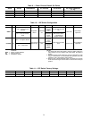
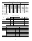
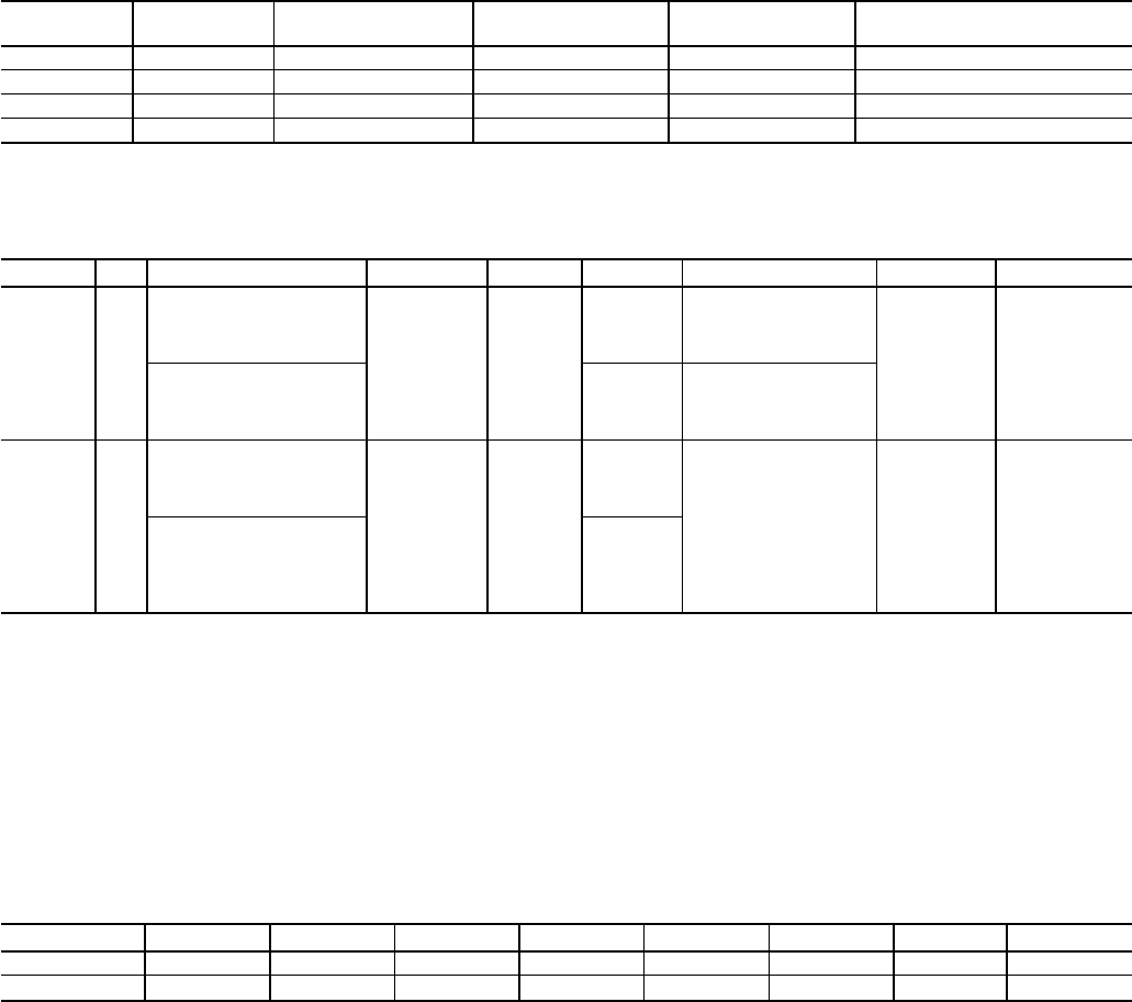
Table 9 — Power Exhaust Default Set Points
STAGE OFFSET DIFFERENTIAL OFF VOLTAGE ON VOLTAGE
OFF STATIC PRESSURE
(in. wg)
1 50% 3% 6.0 6.3 0.00
2 55% 3% 6.5 6.8 0.06
3 60% 3% 7.0 7.3 0.12
4 64% 3% 7.4 7.7 0.18
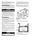
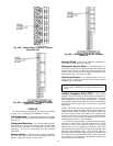
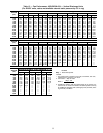
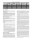
Table 10 — DIP Switch Configuration
SETTING 1 2 3 4 5 6 7 8
OPEN VAV
VAV — Space Sensor
Installed
Expansion
Board
Field Test
ON
VAV —
Occupied
Heat
Enabled
Time Guardா Override
ON
Gas Heat
Heat Pump
Operation
CV — CCN or Sensors
Used
CV —
Modulated
Power
Exhaust
IN CONJUNCTION
WITH FIELD TEST
— Set Minimum
Damper Position
CLOSED CV
VAV — No Space Sensor
Base Control
Board Only
Field Test
OFF
VAV —
Occupied
Heat
Disabled
Time Guard Override
OFF
Electric Heat
Air Conditioner
Operation
CV — Thermostat
CV —
Constant
Volume
Power
Exhaust
LEGEND
CCN — Carrier Comfort Network
CV — Constant Volume
VAV — Variable Air Volume
NOTES:
1. The OPEN side of the DIP switch is marked ‘‘OPEN.’’ When the
rocker switch is on the ‘‘OPEN’’ side of the switch, the switch is
OPEN.
2. The configuration of DIP switches 2 and 5 are dependent on DIP
switch 1. If DIPswitch 1 is set to OPEN(VAV operation), then DIP
switches 2 and 5 will configure VAV functions.
3. When the unit is field-tested (DIP switch 4 to OPEN), the function
of DIP switch 6 changes and itis used to set the minimum damper
position.
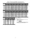
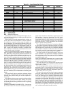
Table 11 — DIP Switch Factory Settings
UNIT 12345678
48EJ,EW Closed Closed Closed Closed Closed Closed Open Closed
48EK,EY Open Closed Closed Closed Closed Closed Open Closed
34