


8
If the furnace is to be suspended from the floor joists in a crawl
space or the rafters in an attic, it is necessary to use steel pipe straps
or an angle iron frame to rigidly attach the furnace to prevent
movement. These straps should be attached to the furnace bottom
side with sheet metal s crews and to the rafters or joists with bolts.
The preferred method is to use an angle iron frame bolted to the
rafters or joists.
If the furnace is to be installed in a crawl space, consult local codes.
A suitable concrete pad or blocks are recommended for crawl space
installation on the ground.
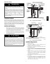
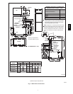
NOTE:6″ (152.4mm) bottom clearance required for condensate
trap.
24″ (609.6mm) inches between the front of the furnace and
adjacent construction or other appliances MUS T be maintained for
service clearance. [30″ (762mm) inches is required to remove
furnace].
Keep all insulating materials clear from louvered door. Insulating
materials may be combustible.
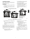
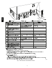
The horizontal furnaces may be installed directly on combustible
wood flooring or supports as long as all required furnace clearances
are met. See Fig. 3.
This furnace MUST NOT be installed directly on carpeting or tile
or other combustible material other than wood flooring or supports.
For horizontal installation over a finished living space. A field
fabricated auxiliary drain pan with drain pipe is required to prevent
damage by overflow due to blocked condensate drain.
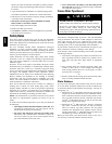
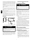
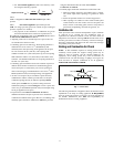
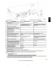
Knock Outs
A07702
Fig. 5 -- Hammer and Screwdriver used for Knockout
CUT HAZARD
Failure to follow this caution may result in personal injury.
Sheet metal parts may have sharp edges or burrs. Use care and
wear appropriate clothing, safety glasses and gloves when
handling parts and servicing furnaces.
CAUTION
!
Use a hammer a nd screwdriver to strike a sharp blow (See Fig. 5)
directly to the knockout tie points or use a hammer in the upper left
corner of the desired knockout. Remove any burrs and sharp edges.
NOTE: If a knockout does not come out after two sharp blows,
pull and snip as needed to remove the knockout.
COMBUSTION & VENTILATION
AIR
For Single Pipe Installation
CARBON MONOXIDE POISONING HAZARD
Failure to follow this warning could result in personal injury
or death.
Use methods described here to provide combustion and
ventilation air.
!
WARNING
Furnaces require ventilation openings to provide sufficient air f or
proper c ombustion and ventilation of flue gases. All duct or
openings for supplying combustion and ventilation air must
comply with the gas codes, or in the absence of local codes, the
applicable national codes.
Combustion a nd ventilation a ir must be supplied in accordance
with one of the following:
NOTE: The Combustion & Ventilation Air Section in this
document, uses tables and information from the ANSI
Z223.1/NFPA 54. For use in Canada, use CSA B149.1 for this
information.
1. Section 9.3, Air for Combustion and Ventilation, of the Na-
tional Fuel Gas Code, (NFGC), ANSI Z223.1 -- 2006/NFPA
54--2006 in the U.S.,
2. Sections 8.2, 8.3, 8.5, 8.6, 8.7, and 8.8 of National Standard
of Canada, Natural Gas and Propane Installation Code
(NSCNGPIC), CSA B149.1--05 in Canada,
3. Applicable provisions of the local building code.
This furnace can NOT be common vented or connected to any type
B, BW or L vent or vent connector, nor to any portion of a
factory--built or masonry chimney. Multistory common venting is
NOT permitted. If this furnace is replacing a previously
common-vented furnace, it may be necessary to resize the existing
vent and chimney to prevent oversizing problems for the other
remaining appliance(s). See “Venting and Combustion Air Check”
in this section. This furnace MUST be vented to the outside.
When the installation is complete, check that all appliances have
adequate combustion air and are venting properly. See Venting And
Combustion Air Check in “Gas Vent Installation” Section in this
manual.
Outdoor Combustion Air Method
A space having less than 50 cubic feet per 1,000 BTUH input rating
for all gas appliances installed in the space requires outdoor air for
combustion and ventilation.
Air Openings and Connecting Ducts
1. Total input rating for all gas appliances in the space MUST
be considered when determining free area of openings.
2. Connect ducts or openings directly to the outdoors.
3. When screens are used to cover openings, the openings
MUST be no smaller than
1
/
4
″ (6.35 mm) mesh.
4. The minimum dimension of air ducts MUST NOT be less
than 3″ (76.2 mm).
5. When sizing a grille, louver, or screen use the free area of
opening. If free area is NOT stamped or marked on grill or
louver, assume a 20% free area for wood and 60% for metal.
Screens shall have a mesh size not smaller than
1
/
4
″ (6.35
mm) .
58HDV