


31
CONCENTRIC VENT
TERMINATION
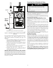
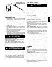
Vent Termination Clearances
CARBON MONOXIDE POISONING, FIRE AND
EXPLOSION HAZARD
Failure to follow this warning could result in personal injury,
death, or property damage.
Inlet and outlet pipes may NOT be vented directly above each
other (standard vent terminals).
!
WARNING
1. Determine termination locations based on clearances
specified in following steps and as shown in Fig. 8, 31
through 36
2. The vent termination must be located at least 12″ (304.8mm)
above ground or normally expected snow accumulation
levels.
3. Do NOT terminate over public walkways. Avoid areas
where condensate may cause problems such as above
planters, patios, or adjacent to windows where steam may
cause fogging.
4. The vent termination shall be located at least 4′ (1.2m)
horizontally from any electric meter, gas meter, gas
regulator, and any relief equipment. These distances apply
ONLY to U.S. installations.
5. The vent termination is to be located at least 3′ (.91m) above
any forced air inlet located within 10′ (3m); and at least 10′
(3m) from a combustion air intake of another appliance,
except another direct vent furnace intake.
6. In Canada, the Canadian Fuel Gas Code takes precedence
over the preceding termination instructions.
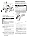
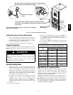
Concentric Vent Termination
Kit # KGAVT0701CVT & KGAVT0801CVT
For additional venting information contact www.Carrier.com.
These kits are for vertical or horizontal termination of t he
combustion air inlet and the exhaust vent pipes on Category IV
gas-- fired condensing furnaces. The KGAVT0701CVT kit can be
used for 2″ (50.8mm) diameter pipe systems. The
KGAVT0801CVT kit can be used for 3″ (76.2mm)diameter pipe
system. Refer to Table 5 for the correct pipe size for the furnace.
Both the combustion air inlet and the exhaust vent pipes must
attach to the termination kit. The termination kit must terminate
outside the structure and must be installed per the instructions
outlined below for vertical or horizontal termination. Vertical
termination is preferred. Field supplied pipe and fittings are
required to complete the installation.
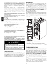
Vertical & H orizontal Termination
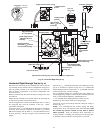
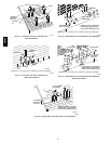
1. Determine the pipe diameters required for the installation
from Table 5 and Fig. 33
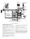
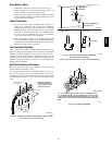
2. Determine t he best location for the termination kit. See Fig.
32 for vertical termination or Fig. 35 and 36 for horizontal
termination. Roof termination is preferred since it is less
susceptible to damage, has reduced intake contaminants and
less visible vent vapor. For side wall termination,
consideration should be given to: 1) possible damage from
the vapors to plants/shrubs, other equipment and building
materials, 2) possible damage to the terminal from foreign
objects, 3) wind effects that may cause recirculation of flue
products, debris or light snow and 4) visible vent vapor.
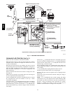
2 (50.8) or 2
1
/
2
″ (63.5)
Dia. SDR--26 Pipe
2″ (50.8) or 3″
(76.2) Dia.
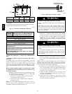
Rain Cap
Nominal 3″ (76.2) or 4″
(101.6) Dia. SDR--26 Pipe
2″ (50.8) or 3″ (76.2) Dia.
Y Concentric Fitting
25-- 22-- 03
Kit Contents:
3″ (76.2) Rain Cap or 2″ (50.8) Rain Cap
3″ (76.2) Diameter SDR--26 Pipe, 19
1
/
2
″ (495.3) Long or
4″ (101.6) Diameter SDR--26 Pipe, 24″ (609.6) Long,
2″ (50.8) Diameter SDR--26 Pipe, 31
5
/
8
″ (803.3) Long or
2
1
/
2
″ (63.5) Diameter SDR--26 Pipe, 37
1
/
8
″ (973) Long,
3″ (76.2) Y Concentric Fitting or 2″ (50.8) Y Concentric Fitting
A07719
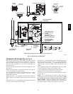
Fig. 31 -- Kit Components
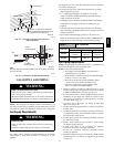
Maintain 12″ (304.8mm)
min. clearance above high-
est anticipated snow level.
Max. of 24″ (609.6mm)
above roof.
Combustion
Air
Roof Boot/
Flashing
(Field Supplied)
Combustion
Air
Vent
Vent
Support
(Field Supplied)
45° Elbow
(Field Supplied)
25--22--02
Note:
Support must be field installed to secure termination kit to structure.
A07720
Fig. 32 -- Concentric Vent Roof Installation
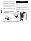
3. Cut one 5″ (127mm)diameter hole through the structure for
the KGAVT0701CVT Kit or one 4″ (101.6mm)diameter
hole for the KGAVT0801CVT Kit .
4. Dimension D may be lengthened to 60″ (1524mm)max. or
shortened by cutting the pipes to 12″ (304.8mm) min.
Dimension A will change according to D dimension. (See
Fig. 33.)
58HDV