


38
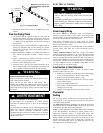
For two--stage thermostat installations, the R, W1 and W2 wires
from the thermostat connect to the R, W1 and W2 connections on
the furnace control board. Set TT SW1 DIP switch #3 to ON
position. During operation, the furnace will shift from Low Heat to
High Heat as requested by the thermostat. (See Fig. 40 and wiring
diagram)
Heat anticipator setting will need to be measured if 24VAC
humidifier is installed. Measure current in series from R to W1 at
the thermostat. Be sure 24VAC humidifier is operating during this
check. Allow furnace to operate for 2 minutes before recording the
AC amperage reading. Set anticipator on thermostat to recorded
value.
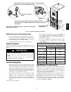
Thermostat location has an important effect on the operation of the
furnace. Follow instructions included with thermostat for correct
mounting and wiring.
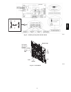
Low voltage connections to furnace must be made on terminal
board to furnace control board. (See Fig. 41)
Cooling
If single-- speed cooling is used, the YandGfrom the thermostat
must be connected to the control board Y/Y2 and G to energize
cooling blower speed.
If two--stage cooling is used, the Y1, Y2, G of the thermostat must
be connected to Y1 of tap select interface board for low cooling,
Y/Y2 of the furnace control board for high cooling and G of the
furnace control board for continuous fan speed.
Optional Equipment
All wiring from furnace to optional equipment MUST conform to
local codes or, in the absence of local codes with the latest edition
of The National Electric Code, ANSI NFPA 70 and/or The
Canadian Electric Code CSA C22.1. Install wiring in accordance
with manufacturer’s instructions. The wiring MUST have a
minimum temperature rating of 105° C.
Humidifier/Electronic Air Cleaner
The furnace is wired for humidifier and/or electronic air cleaner
connection.
HUMIDIFIER -- The HUM (24V) terminal is energized when the
low pressure switch closes on a call for heat. The HUM (115V) is
energized when the inducer is energized.
ELECTRONIC AIR CLEANER -- EAC terminal is energized
when there is a blower speed call, except it is NOT energized when
blower operates in the hard-- wired continuous fan mode.
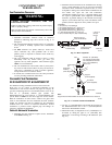
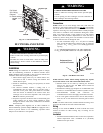
REDUCED FURNACE LIFE HAZARD
Failure to follow this caution may result in reduced furnace
life.
Do NOT exceed 115V/1.0 amp. maximum current load for
both the EAC terminal and the HUM terminal combined.
CAUTION
!
Furnace Control B oard
The furnace control board has a fixed blower ON delay of 30
seconds for High Heat calls and 45 seconds for Low Heat calls. The
blower OFF timing is factory preset at 140 seconds. If desired, the
fan OFF delay can be reset to obtain the longest delay times while
still maintaining comfort levels. See “Furnace Wiring Diagram”.
Dehumidification
The furnace control board has a dehumidification feature which
reduces cooling airflow by 20% when the DEHUM terminal (
1
/
4
”
male quick connect) is energized by 24VAC and there is a cooling
call. DEHUM may be operated by a thermostat dehumidify
(24VAC for dehumidify) command or a dehumidistat (switch closes
on call for dehumidification) with one terminal connected to (Y1
for t wo--stage cooling or Y/Y2 for single--speed cooling
applications) and the other terminal connected to DEHUM.
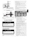
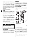
Furnace Control Fuse
The 24V circuit contains a 5--amp, automotive--type fuse located on
furnace control board. (See Fig. 41) Any electrical shorts of 24V
wiring during installation, service, or maintenance may cause fuse
to blow. If fuse replacement is required, use only a fuse of identical
size (5 amp.)
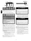
C
W2
R
W1
G
C
Y/Y2
W2
R
W1
G
Y/Y2
W2
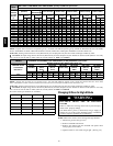
*
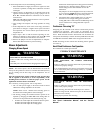
Permissible limits of voltage at which unit will operate satisfactorily
Connection
Box
NEUT
.
HOT
Ground
115V. 60 Hz.
G
R
W1
G
G
TerminalBoard
LowV oltage
Thermostat
T woStage
Operatingvoltagerange*:127VACmax,104VACmin.
NOTE:115VAC/60Hz/single----phase
Thermostat
SingleStage
R
W
TerminalBoard
LowV oltage
BK
W
A07779
Fig. 40 -- Electrical Connections
Tap Select Interface Board
The T ap Select Interface Board is used with the Variable Speed
motor. There are DIP switches (SW2) for continuous blower adjust,
heating blower adjust, cooling blower adjust and cooling on/off
delay profiles. There is a jumper (J1) for slight blower adjustment,
increase (+)/no change (NOM)/decrease (--). There is a jumper (J2)
for airflow selection of Heat Pump EFFICIENCY or COMFORT.
(EFFICIENCY provides no airflow reduction in airflow whether
O is energized or not. COMFORT provides a 10% reduction in
airflow when O is not energized with a cooling call).
The O terminal is available f or use for Heat Pump applications, if
desired.
The Y1 terminal (if a two--stage Air Conditioner or t wo--stage Heat
Pump is used) will provide low cooling blower speed when
energized. (Only Y/Y2 on the furnace control board is used if a
single--stage Air Conditioner or Heat Pump is installed)
58HDV