


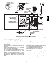
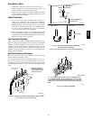
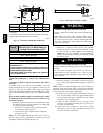
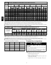

32
B
PVC Intake/Combustion Air
B PVC
Vent/Exhaust
D
A
1
1
/
2
″
C
Model A* B C D**
KGAVT0801CVT 38
7
/
8
3 4
1
/
2
21
1
/
8
KGAVT0701CVT 33
3
/
8
2 3
1
/
2
16
5
/
8
* = Dimension will change accordingly as dimension D is lengthened
or shortened.
**= Dimension D may be lengthened to 60″ may also be shortened by
cutting the pipes provided in the kit to 12″ minimum.
(38 mm)
A09195
Fig. 33 -- Concentric Vent Dimensional Drawing
Table 5
Concentric Termination Kit
KGAVT0701CVT & KGAVT0801CVT
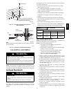
Venting Table Dual Piping ONLY
40,000, 50,000, 60,000, & 75,000 Btuh Furnaces
KGAVT0701CVT -- 35′ (10.7m) & (4) 90° elbows
with 2″ (50.8mm) PVC pipe
80,000, 100,000 & 125,000 Btuh Furnaces
KGAVT0801CVT -- 35′ (10.7m) & (4) 90° elbows
with 3″ (76.2mm) PVC pipe
1. Do not include the field supplied 45° elbow in the
total elbow count.
2. If more than four elbows are require d, reduce the
length of both the inlet and the exhaust pipes five feet
for each additional elbow used.
3. Elbows are DWV long radius type for 2
″ (50.8mm)
and 3
″ (76.2mm) vents.
If more than four elbows are required, reduce the length of both
the inlet and exhaust pipes 5′ (1.5m)for each additional elbow
used.
* Feet of pipe is whichever pipe run is the longest, either inlet or
outlet side.
If assembly needs to be extended to meet height or side wall
thickness requirement, the two pipes supplied in the kit may be
replaced by using t he same diameter solid, single ( no coupling
connections) field supplied SDR-- 26 PVC (ASTM D2241) pipes.
Do not extend dimension D more than 60″(1524mm). (See Fig.
33.)
Do not use field supplied couplings to extend the pipes. Airflow
r estriction will occur and the furnace pressure switch may cause
intermittent operation.
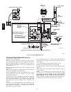
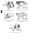
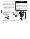
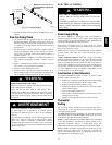
5. Partially assemble the concentric vent termination kit. Clean
and cemen t the parts using the procedures for Joining Pipe
and Fittings section of the manual.
a. Cement the Y Concentric fitting to the longest of the
two straight kit pipes. See Fig. 34.
b. Cement the rain cap to the shortest of the straight kit
parts. (See Fig. 34.)
NOTE: A field s upplied s tainless steel screw may be used to
secure the rain cap to the pipe instead of cementing when field
disassembly is desired for cleaning (See Fig. 34.)
Drill clearance hole in rain
cap and pilot hole in vent pipe.
Stainless steel screw
(Field supplied)
A07722
Fig. 34 -- Rain Cap to Vent Pipe Assembly
CARBON MONOXIDE POISONING HAZARD
Failure to follow this warning could result in personal injury
or death.
When using the alternate screw assembly method, drill a
clearance hole in the rain cap and a pilot hole in the vent pipe
for the screw size being used. Failure to drill adequate holes
may cause cracking of the PVC components, allowing flue
gasses to be recirculated.
!
WARNING
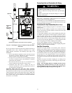
6. Install the Y concentric fitting and the pipe assembly
through the structure’s hole. For vertical termination, install
the parts through the field supplied roof boot/flashing.
NOTE: Do not allow insulation or other materials to
accumulate inside the pipe assembly when installing through
the structure’s hole.
CARBON MONOXIDE POISONING HAZARD
Failure to follow this warning could result in personal injury
or death.
Do not operate the furnace with the rain cap removed as
recirculating of the flue gasses may occur. Water may also
collect inside the larger combustion air pipe and flow to the
burner enclosure.
!
WARNING
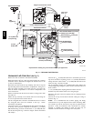
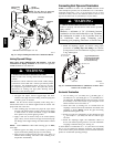
7. Secure the assembly to the s tructure as shown in Fig. 32 or
Fig. 36 using field supplied metal strapping or equivalent
material.
NOTE: Ensure the termination height is above the roof surface or
anticipated snow level as shown in Fig. 32 for vertical termination.
Ensure the termination l ocation clearance dimensions are as shown
in Fig. 35 and Fig. 36 for horizontal termination.
8. Install the rain cap and the small diameter pipe assembly in
the Y concentric fitting and the large pipe assembly. Ensure
that the small diameter pipe is bottomed out and securely
cemented in the Y concentric fitting.
9. Cement the furnace combustion air and vent pipes to the
concentric vent termination assembly. See Fig. 32 or Fig. 36
for proper pipe attachment.
10. Operate the furnace through one heat cycle to ensure
combustion air and vent pipes are properly connected to the
concentric termination connections.
58HDV