


46
SEQUENCE OF OPERATION & DIAGNOSTICS
The following is the normal operating sequence at factory default settings (SW1 OFF/ON/OFF, SW2 all OFF)
NOTE: SW1 DIP switches (G, Y/Y2, W1, W2 thermostat terminals) and DEHUM (1/4” male quick connect terminal) are located on the
FCB.
SW2 DIP switches and Y1 and O thermostat terminals are located on the TSIB.
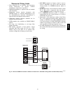
Low Cooling (Y1) Request:
24VAC signals applied to Y1 & G terminals of TSIB (Tap Select Interface Board) and FCB (Furnace Control Board), respectively.
S Low Cooling motor speed is energized after 5 second Cool Fan On Delay time.
Y1 & G signals removed from TSIB and FCB
S Low Cooling motor speed is de--energized after 90 second Cool Fan Off Delay time. Cooling (Y1) and dehumidification (DEHUM)
requests:
S 24 VAC signals applied to Y1, DEHUM & G terminals of TSIB and FCB.
S Same operation as the cooling (Y1) request, except the cooling airflow is reduced 20% to compensate for high humidity conditions during
cooling operation. The low cooling airflow returns to the normal setting after the DEHUM signal is removed.
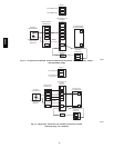
High Cooling (Y1 & Y/Y2) or (Y/Y2) Reques t:
24VAC signals applied to Y1 & Y/Y2 & G or Y/Y2 & G terminals of FCB (Furnace Control Board).
S High Cooling motor speed is energized after 5 second Cool Fan On Delay time.
Y1 & Y/Y2 & G or Y/Y2 & G signals removed from TSIB and FCB
S High Cooling motor speed is de--energized after 90 second Cool Fan Off Delay time.
High Cooling (Y1 & Y/Y2 or Y/Y2) and dehumidification (DEHUM) requests:
S 24 VAC signals applied to Y1 & Y/Y2 or Y/Y2, DEHUM, & G terminals of TSIB and FCB.
S Same operation as the high cooling (Y1 & Y/Y2 or Y/Y2) request, except the cooling airflow is reduced 20% to compensate for high
humidity conditions during cooling operation. The high cooling airflow returns to the normal setting after the DEHUM signal is removed.
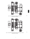
Low or high cooling and O terminal (Heat Pump mode):
S If the J2 jumper is in the AC/HP EFFICIENCY position, there will be no change in blower airflow regardless of the O terminal being
energized or de--energized.
S If the J2 jumper is in the HP COMFORT position, then there will be a 10% reduction in airflow when the O terminal is de-- energized (HP
heating) and no airflow reduction when O is energized (HP cooling).
NOTE 1) The motor has been set up to recognize the O terminal as energized during cooling calls (reversing valve energized for cooling).
Continuous Circulating Fan (G) Request:
24VAC signal applied to G terminal of FCB.
S Continuous fan speed is energized without delay.
G signal removed from FCB.
S Continuous fan speed is de-- energized after 5 second delay.
NOTE 2) Heat or Cooling requests received during a Fan request, cause the fan speed to change to the appropriate heat or cool speed after the
Fan On Delay time expires. The fan returns to continuous circulating speed after the selected Fan Off Delay time expires following loss of the
Heating or Cooling request.
NOTE 3) Hard--wire option not available for variable speed models.
NOTE 4) Continuous blower selection DIP 10 and 11 will cause the blower to run in high cooling speed for all low cooling (Y1) calls.
Continuous blower DIP settings of 00 and 01 will allow low cooling (Y1) calls to operate normally.
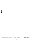
Heating (W1) Request (single stage thermostat operation, SW1 DIP switch #3 on the FCB
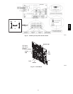
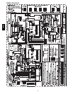
must be in OFF position) (see furnace wiring diagram):
24VAC signal applied to W1 terminal of FCB.
S Inducer motor turns on at high speed.
S Following a 15 second prepurge delay after the low pressure switch closes, the igniter begins a 17 second warm up.
S The gas valve is energized, the main burners light at Low Heat rate.
S The igniter is de--energized, and the inducer drops to low speed after the main burners ignite.
S The FCB will delay Low Heat blower operation for the 45-- second Low Heat Fan On Delay time timed from the opening of the gas valve.
S If the W1 request is still present after 12 minutes, timed from the opening of the gas valve, the inducer switches to high speed, closing the
high pressure switch, then the High Heat solenoid energizes, and the fan switches to High Heat speed.
W1 signal removed from FCB.
S The gas valve de--energizes and the main burners go out.
S The inducer runs at its present speed for a 15 second postpurge period.
S The fan runs at its present speed.
S The blower de--energizes after the selected Heat Fan Off Delay time expires timed from the gas valve de--energizing.
58HDV