


27
Open Tee
Tee Trap
Condensate
Trap
Evaporator
Coil
Drain Line
(Optional)
Main
Drain
Line
INLET
EXHAUST
IN
ON
OFF
V
E
N
T
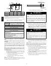
Representative drawing only, some models may vary in appearance.
A07713
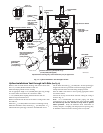
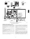
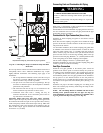
Fig. 20 -- Connecting Tee Trap to Condensate Trap and Main
Drain Line
The tee trap must be connected to the main condensate drain line as
conceptually shown above. Different installations may require
slightly different orientations. The following steps apply to all
installations.
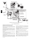
1. The tee trap should be installed as close to the side or top of
the furnace as practical. Minimize the distance between the
inducer and the tee trap as much as possible.
2. An open tee is to be used at the tee trap discharge. The top
end of the tee should be open to the atmosphere to eliminate
potential air lock problems.
3. The drain line from the tee trap is to be connected to the
furnace condensate trap drain line as shown above.
4. Condensate drain lines from a cooling coil may be
connected downstream of the connection point of the tee
trap and furnace condensate trap.
Important: Prime both t raps with water befor e operation.
Failure to prime the traps may result in discharge of flue gases from
the condensate drain line and open tee for a period of time, and may
result in temporary lockout of the furnace upon start up. Main drain
line construction is left to the discretion of the installer. It may be
made of either ridged pipe or flexible tube. Tube ID should NOT
be less than
1
/
2
″
(12.7mm).
Connecting Vent and Combustion Air Piping
CARBON MONOXIDE POISONING HAZARD
Failure to follow this warning could result in personal injury
or death.
Cement or mechanically seal all joints, fittings, etc. to prevent
leakage of flue gasses.
!
WARNING
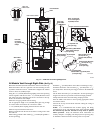
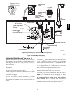
Refer to Fig. 11 through Fig. 19 that corresponds to the installation
position of the furnace for the application.
Preassemble the vent and combustion air piping from the furnace to
the vent termination. Do not cement t he pipe joints until the pipe
preassembly process is complete.
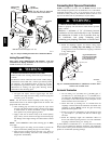
Combustion Air Pipe Connection ( Direct Vent)
Install the air intake coupling and gasket to the furnace with the
four(4) screws.
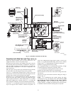
Note: The air intake coupling and gasket can be installed to the top
panel to the alternate air intake locations on either the left or right
side panels of the furnace.
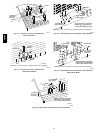
For downflow installation, the air intake coupling and gasket must
be installed t o the alternate air intake location on either the left or
right side panels. Remove the 3″ (76.2mm) hole plug from the
furnace accessory bag and relocate to the open hole in the furnace
panel. Use four screws to seal the four mounting holes in the top
panel next to the hole plug. Drill four
7
/
64
″ (2.8mm) diameter holes
in the casing using the air intake coupling as the template.
The air intake coupling is sized for 2″ (50.8mm) PVC pipe.
Install the combustion air pipe to the air intake coupling using RTV
sealant to provide for future serviceability.
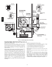
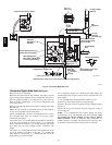
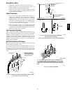
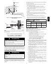
Vent Pipe Connection
Install the vent pipe grommet to the furnace panel. Locate the
grommet in the furnace panel at a location directly away from the
vent fitting on the combustion blower. The grommet snaps into the
3″ (76.2mm) hole from the furnace panel. NOTE: Depending on
the installation position, the vent pipe grommet will be installed to
the top panel or to the alternate location on the side panels. If
needed, remove the 3″ (76.2mm) hole plug from the loose parts bag
and install it in the open hole in the furnace panel. (See Fig. 11 or
Fig. 20)
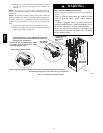
Install the vent pipe to the rubber coupling, the vent fitting or the
PVC vent extension pipe. Securely attach using the clamp or PVC
cement as required.
NOTE: The vent f itting MUST be installed with the air flow
marking arrow pointed toward the vent pipe. (See Fig. 21).
Some installations require the vent fitting to be installed with a
5° to 10° downward slope. (See Fig. 1 1 thru Fig. 20)
58HDV