


40
2. Insulate ductwork in indoor unconditioned areas with a
minimum of 1″ (25.4mm) insulation with indoor type vapor
barrier .
Filters
A filter must be used:
Filters are supplied with these furnaces, and additional filters may
be purchased from your distributor.
Use either filter type:
S Washable, high velocity filters are based on a maximum
air flow rating of 600 FPM.
S Disposable, low velocity filters are based on a maximum
air flow of 300 FPM when used with filter grille.
S See Service & Maintenance Manual, Circulation Air
Blower Data for additional data.
NOTE: Disposable, low velocity filters may be replaced with
washable, high velocity filter providing they meet the minimum
size areas. Washable, high velocity filters can be replaced ONLY
with same type and size.
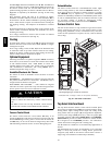
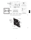
A07729
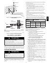
Fig. 43 -- Side Mounted Filter Rack
Filter Installation using Filter Rack
When installing or removing a bottom mounted filter, slide the two
side filter clips to the back of the furnace BEFORE installing or
removing. This will allow the filter to clear the front raised edge of
the furnace. Insert filter into side clips first and push filter back until
it is fully engaged into back clip. When filter is in place, slide clips
back into place midway on filter as shown in Fig. 44 or Fig. 45
Slide filter clips towards back before removing
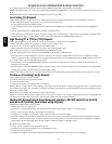
25--24--18--1
Center Clip
side --to-- side
9″ (152.4mm)
A07691
Fig. 44 -- Bottom Mounted Filter Rack
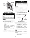
3″
1
1
/
4
″
1
1
/
2
″
11
/
16
″
26 Ga. Galvanized Steel
FAST part number 1008482
(38.1)
(31.8)
(76.2)
(27)
A07730
Fig. 45 -- Filter Clip Construction
Refer to Fig. 46 and for guidelines to install filters. Furnaces which
require larger filter media and have limited clearances on one side
of furnace, require a standoff filter rack, see Fig. 46, available from
your distributor.
NOTE: If filters are only suitable for heating application,
advise homeowner that filter size may need to be increased if
air conditioning is added.
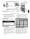
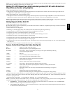
Using Optional
Standoff Filter
Rack
A07731
Fig. 46 -- Standoff Filter Rack
Addition Of Air Conditioning
When a refrigeration coil is used in conjunction with this unit, it
must be installed parallel with or on the discharge side of the unit to
avoid condensation on the heat exchanger. All furnaces are
designed with a break--away duct flange on the supply air side of
the furnace. This allows for installation in the horizontal right or
downflow applications. The coil installation instructions must be
consulted for proper coil location and installation procedures. With
a parallel flow arrangement, dampers must be installed to prevent
chilled air from entering the furnace. If manually operated dampers
are used, they must be equipped with a means to prevent operation
of either unit unless the damper is in full heat or full cool position.
A3″ clearance is required on the right side of the furnace in order to
run the condensate drain line. Copper or plastic tubing may be used
for the condensate drain line.
Downflow Furnace Installation
Non- Combustible Floor Installation
Fabricate a plenum to the dimensions given in Fig. 47, for the
furnace outlet. Plenum should be flanged, approximately
3
/
4
″
(19.1mm) for support.
58HDV