


37
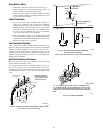
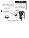
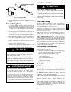
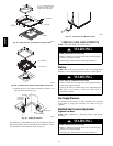
Measure from face of ori-
fice to theback side of the
manifold.
1.11″ (28.2mm)
1.21″ (30.8mm)
A07725
Fig. 39 -- Changing Orifices
5. Reinstall manifold. Ensure burners do NOT bind on new
orifices.
Final Gas Piping Check
1. The furnace and the equipment shut off valve must be
disconnected from the gas supply piping system during any
pressure testing of that system at test pressures in excess of
1
/2″ PSIG. Close the manual shut--off valve before testing at
such pressures.
2. The furnace must be isolated from the gas supply system by
closing the equipment shut off valve during any pressure
testing of the gas supply system at test pressure equal to or
less than
1
/2″ PSI.
3. When installation is complete, test all pipe connections for
leaks with the gas pressure less than
1
/2″ PSIG to the gas
valve.
4. Apply a commercial soap solution to all joints to test for
leaks. Correct any leaks indicated by bubbles.
5. Correct even the smallest leak at once.
6. Check for leaks at gas valve and orifice connections to the
burner manifold along with the pilot tube connections to the
valve and pilot assembly while the furnace is operating.
FIRE OR EXPLOSION HAZARD
Failure to follow this warning could result in personal injury,
death, and/or property damage.
Never test for gas leaks with an open flame. Use a
commercially available soap solution made specifically for the
detection of leaks to check all connections. A fire or explosion
could result causing property damage, personal injury and/or
loss of life.
!
WARNING
RISQUE D‘INDENDIE OU D‘EXPLOSION
Le non--respect des avertissements de sécurité pourrait
d‘entrainer des blessures graves, la mort ou des dommages
matériels.
Ne jamais utiliser une flamme nue por vérifier la présence des
fuites de gaz. Pour la vérification de tous les joints, utiliser
plutôt une solution savonneuse commerciale fabriquée
spécifiquement pur la détection des fuites de gaz. Un incendie
ou une explosion peut entrainer des dommages matériels, des
blessures ou la mort.
!
AVERTISSEMENT
ELECTRICAL WIRING
ELECTRICAL OPERATION HAZARD
Failure to follow this warning could result in personal injury
or death.
Turn OFF electrical power at fuse box or service panel
before making any electric al connections and ensure a
proper ground connection is made before connect ing
line voltage.
!
WARNING
Power Supply Wiring
The furnace MUST be electrically wired and grounded in
accordance with local codes, or in the absence of local codes with
the latest edition of The National Electric Code, ANSI NFP A 70
and/or The Canadian Electric Code CSA C22.1.
Field wiring connections must be made inside the furnace
connection box. A suitable strain relief should be used at the point
the wires exit the furnace casing.
NOTE: Furnace will not have normal operation is line polarity is
reversed. Check ALL field and control connections prior to
operation.
Copper conductors shall be used. Line voltage wires should
conform to temperature limitation of 35° C rise and be sized for the
unit maximum amps stated on the rating plate. Add the full load
amps for potential field--installed accessories such as electronic a ir
cleaners and humidifiers that would receive power from the furnace
control board. The furnace control board is rated for a maximum of
1.0 amps combined for EAC and HUM. Consult NEC or local
codes for proper wire and circuit sizing.
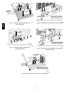
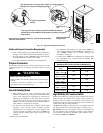
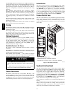
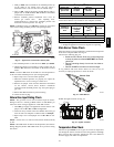
Junction Box (J- Box) Relocation
The J--Box i s installed on left side of casing. An alternate J--Box
location on right side can be used.
1. Remove bag containing two hole plugs and two self tapping
screws from loose parts bag in blower compartment.
2. Remove two screws holding J--Box to casing.
3. Install large hole plug from loose furnace accessory bag into
the left J--Box location.
4. Clip wire tie holding J--Box wires.
5. Move J--Box to alternate location and attach using t wo self
tapping screws from bag.
6. Apply two hole plugs from bag at left J--Box location.
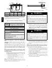
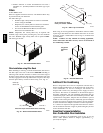
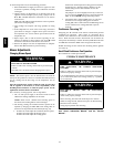
Thermostat
Heating
The two--stage furnace control board will operate with either a
single stage or a two-- stage heating thermostat and will provide
two--stage heating operation.
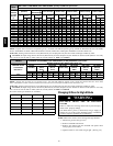
For single--stage thermostat installations, the R and W wires from
the thermostat connect to the R and W1 connections on the furnace
control board. (See Fig. 40and wiring diagram)
NOTE: The TT (Thermostat Type) SW1 DIP switch #3 should be
in the OFF position for the furnace to operate properly with a
single--stage thermostat. Failure to change DIP switch with
single--stage thermostat will result in Low Heat operation ONLY.
During operation, the furnace will operate on Low Heat for up to12
minutes. If the heat request exists for more than 12 minutes, the
furnace will automatically shift to the High Heat mode for the
remaining duration of the heating cycle.
58HDV