


13
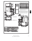
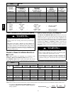
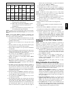
Applicable ASTM Standards for V e nt Materials
Materi-
als
Sch. 40
Pipe
SDR
Pipe
Cell
Core
Pipe
Fittings Primer
Solv.
Cement
ABS D1527 __ F628
D2468
&
D2661
-- -- D2235
PVC D1785 D2241 F891
D2466
&
D2665
F656 D 2564
CPVC F441 F442 -- -- F438 -- -- F 493
ABS to
PVC
-- -- -- -- -- -- -- -- -- -- D3138
(2.) Only use solvent cements that are marked for use
with the specific venting material.
(3.) ABS to PVC transition joints REQUIRE a special
solvent cement that meets the requirements of
ASTM D3138.
(4.) Refer to ASTM D2855 for general procedure to use
for cementing plastic pipe and fittings.
NOTE: In order to create a seal that allows future removal of pipe,
RTV sealant MUST be used on the inlet pipe where it joins to the
furnace.
NOTE: All vent piping MUST be installed in compliance with
local codes or ordinances, these instructions, good trade practices,
and codes of country having jurisdiction.
1. Determine the best routing and termination f or the vent pipe
and air inlet pipe by referring to all of the instructions and
guidelines in this Section.
2. Determine the size required for the vent pipe and air inlet
pipe.
3. Loosely assemble all venting parts without adhesive (pipe
joint cement) for correct fit before final assembly.
4. Furnace shall be installed so as to prevent the accumulation
of condensate.
5. Use of vertical piping is preferred because there will be some
moisture in the flue gases that may condense as it leaves the
vent pipe (See Instructions for Horizontal Vents).
6. The vertical vent pipe MUST be supported so that no
weight is allowed to rest on the combustion blower.
7. Exhaust vent piping or air inlet piping diameter MUST
NOT be reduced.
8. All exhaust vent piping from the furnace to termination
MUST slope upwards. A minimum of
1
/
4
″ (6.4mm) per foot
(304.8mm) of run is required to properly return condensate
to the furnace drain system.
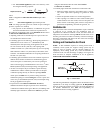
9. Use DWV type long radius elbows whenever possible, as
they provide for the minimum slope on horizontal runs and
they provide less resistance in the vent system. If DWV
elbows cannot be used, use two, 45° elbows when possible.
On horizontal runs the elbows can be slightly misaligned to
provide the correct slope.
10. All horizontal pipe runs MUST be supported at least every
five feet (1.5 M) with galvanized strap or other rust resistant
material. NO sags or dips are permitted.
11. All vertical pipe runs MUST be supported every six feet
(4.8 M) where accessible.
12. The maximum pipe length is 40′ (12.2m) total in the inlet or
outlet side of the system. Up to five, 90° elbows can be used
on the inlet or the outlet. With the Concentric Vent
Termination Kits (KGAVT0701CVT or KGAVT0801CVT),
the maximum pipe length is 35′ (10.7m) with four 90°
elbows. If more elbows are required, reduce the length of
both the inlet and exhaust pipes 5′ (1.5m) for each additional
elbow used. (See Table 3 or Table 4).
13. The minimum vent length is 5′ (1.5m) of PVC.
14. The piping can be run in the same chase or adjacent to
supply or vent pipe for water supply or waste plumbing. It
can also be run in the same chase with a vent from another
90+ furnace.
NOTE:InNO case can the piping be run in a chase where
temperatures can exceed 140° F(60° C). or where radiated heat
from adjacent surfaces would exceed 140° F(60° C).
15. The vent outlet MUST be installed to terminate in the same
atmospheric pressure zone as the combustion air inlet.
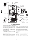
16. The vent system can be installed in an existing unused
chimney provided that:
S Both the exhaust vent and air intake run the length of the
chimney .
S No other gas fired appliance or fireplace (solid fuel) is vented
into the chimney.
S The top of the chimney MUST be sealed flush or crowned up to
seal against rain or melting snow so ONLY the piping protrudes.
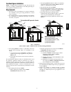
S The termination clearances shown in Fig. 8 are maintained.
17. Furnace applications with vertical vents requiring vent
diameter increaser fittings must have increaser fittings
installed in vertical portion of the vent. Condensate will be
trapped in the vent if the vent diameter is increased prior to
having an elbow turned upward. This could cause nuisance
tripping of the pressure switch.
Combustion Air and Vent Piping Insulation
Guidelines
NOTE: Use closed cell, neoprene insulation or equivalent. If
Fiberglass or equivalent insulation is used it must have a vapor
barrier. Use R values of 7 up to 10′ (3.1m), R-- 11 if exposure
exceeds 10′ (3.1m). If Fiberglass insulation is used, exterior to the
structure, the pipe MUST be boxed in and sealed against moisture.
1. When the vent or combustion air pipe height above the roof
exceeds 30″ (76.2mm),orifanexteriorverticalriserisused
on a horizontal vent to get above snow levels, the exterior
portion MUS T be insulated.
2. When combustion air inlet piping is installed above a
suspended ceiling, the pipe MUST be insulated with
moisture resistant insulation such as Armaflex or other
equivalent type of insulation.
3. Insulate combustion air inlet piping when run in warm,
humid spaces.
Sizing Combustion Air and Vent Pipe
Consult Table 3 or Table 4 to select the proper diameter exhaust and
combustion air piping. Exhaust and combustion air piping is sized
for each furnace Btuh size based on total lineal vent length (on inlet
or outlet side), and number of 90° elbows required.
1. Double Pipe Installation--If installing a s a direct--vent
appliance, consult Table 4 to select the proper diameter
exhaust and combustion air piping. Exhaust and combustion
air piping is sized for each furnace Btuh size based on total
lineal vent length (on inlet or outlet side), and number of
90° elbows required.
2. Single Pipe Installation--If installing as a non--direct vent
appliance, (single outlet pipe a nd no inlet pipe) refer to
Table 3. The table shows the maximum number of elbows
allowed with any given pipe diameter and length of run.
3. Use of Elbows-- Two 45° elbows can be substituted for one
90° elbow. The elbow or elbows used for vent termination
outside the structure ARE counted, including elbows needed
to bring termination above expected snow levels.
58HDV