


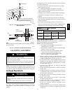

41
Note: The three(3) screws in the top panel of the furnace next to the
duct flange MUST be removed to provide serviceability of the
primary heat exchangers in the downflow installation
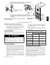
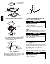
1. Position plenum through the floor and set the furnace over
the opening in the floor. If necessary, grout around the base
to seal air leaks between the base and the floor.
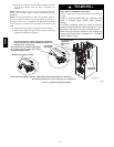
Combustible Floor Installation
FIRE HAZARD
Failure to
install unit on noncombustible subbase could
result in personal injury, death, and/or property
dama ge.
Place furnace on noncombustible subbase on
downflow applications, unless installing on non--
combustible flooring. The nonc ombustible subbase
also must be used on downflow applications in
addition to a coil box installation.
!
WARNING
Subbase for Combustible Floor
NOTE: The three(3) screws in the top panel of the furnace next to
the duct flange MUST be removed to provide serviceability of the
primary heat exchangers in the downflow installation
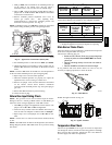
Note: When using the subbase for combustible floors, the discharge
air duct flanges on the furnace MUST be broken down to provide
proper fit up to the subbase. Use duct pliers to bend the duct flanges
flat onto the furnace casing. DO NOT bend the duct flanges inward
(toward the heat exchangers) as air flow restrictions may occur.
The Subbase for Combustible Floors MUST be used when a
downflow furnace is set on a combustible floor, even when the
furnace is installed on a coil box.
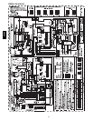
1. Cut t he opening in the floor according to Table 9. The hole
in the floor must be cut to the dimensions listed in Table 9
since the base is equipped with locating tabs that center the
base over the opening.
The opening in the base is 1
1
/
4
″ (31.8mm) shorter and 1
1
/
8
″
(28.6mm) narrower than the recommended size of the opening in
the floor. This is done to maintain clearance between the floor and
the plenum.
2. Fabricate the plenum to the dimensions given in Table 9.
Note that the dimensions given are outside dimensions.
3. Set the base over the opening in the floor, centering it over
the opening. Fasten the base to the floor with screws or nails.
See Fig. 47, 48, and 49.
4. Drop the plenum through the opening in the base. The
flange of the plenum should rest on top of the subbase.
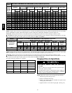
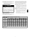
Table 9 Subbases for Combustible Floors Dimensions -- in(mm)
Sub--base for
Combustible Floors
Part Number
Sub--base for Combustible
Floor Dimensions
Opening In Floor
Opening In
Base For Plenum
Typical Plenum
Dimensions
H
*
J* K** L M N P R S T
Furnace Only
KGASB0301P01
19
5
/
16
(490.5)
28
3
/
4
(730.3)
18
3
/
16
(462)
16(406.4)
16
1
/
4
(412.8)
18
1
/
4
(463.6)
15 (381)
17
1
/
8
(435.6)
15 (381)
17
1
/
8
(435.6)
KGASB0401P02
22
15
/
16
(582.6)
28
3
/
4
(730.3)
21
13
/
16
(554)
16(406.4)
16
1
/
4
(412.8)
21
7
/
8
(555.6)
15 (381)
19
3
/
4
(501.7)
15 (381)
19
3
/
4
(501.7)
KGASB0801P06
24
11
/
16
(627.1)
28
3
/
4
(730.3)
23
9
/
16
(598.5)
16(406.4)
16
1
/
4
(412.8)
23
5
/
8
(600.1)
15 (381)
22
1
/
2
(571.5)
15 (381)
22
1
/
2
(571.5)
Subbase for Coil Box
KGASB0501P03
19
3
/
8
(181.1)
20
9
/
16
(522.3)
18
3
/
16
(462)
16
1
/
16
(408)
16
1
/
4
(412.8)
18
1
/
4
(463.6)
15 (381)
17
1
/
8
(435.6)
15 (381)
17
1
/
8
(435.6)
KGASB0601P04 23 (284.2)
20
9
/
16
(522.3)
21
13
/
16
(554)
16
1
/
16
(408)
16
1
/
4
(412.8)
21
7
/
8
(555.6)
15 (381)
19
3
/
4
(501.7)
15 (381)
19
3
/
4
(501.7)
KGASB0701P05
24
3
/
4
(628.7)
20
9
/
16
(522.3)
23
9
/
16
(598.5)
16
1
/
16
(408)
16
1
/
4
(412.8)
23
5
/
8
(600.1)
15 (381)
22
1
/
2
(571.5)
15 (381)
22
1
/
2
(571.5)
*
Outside Dimension
**
Base Spacer Side To Side
Conversion: 1 in = 25.4 mm
58HDV