


17
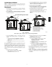
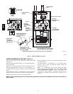
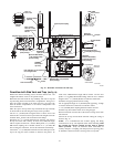
Condensate Drain Trap
This furnace removes both sensible and latent heat from the
products of combustion. Removal of the latent heat results in
condensation of the water vapor. The condensate is removed from
the furnace through the drains in the plastic transition and the vent
fitting. The drains connect to the f actory installed internally
mounted condensate drain trap on the left or right side of the
furnace.
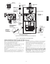
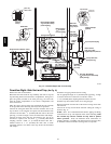
The startup of a new furnace will involve a cycle or two of the
furnace to properly prime the condensate trap with water. Until the
trap is fully primed, some condensate will be pulled into the
combustion blower. The furnace may cycle on the pressure switch
connected to the plastic transition box due to condensate buildup.
After the trap is primed, the condensate will start draining from the
furnace. The combustion blower will clear out any remaining
condensate in the blower housing through the vent fitting
downstream of the blower. Note that the condensate trap can also be
primed by pouring water into the
1
/
2
″ (12.7mm) drain hose.
Remove the
1
/
2
″ (12.7mm) ID drain hose from either the gutter or
the white PVC tee trap. Using a funnel pour eight (8) ounces (30
ml)ofwaterinto
1
/
2
″ (12.7mm) ID drain hose. Water will flow
through the drain hose and into the condensate drain trap. This will
prime both the vent and the transition sides of the trap. Reconnect
the
1
/
2
″ (12.7mm) ID drain hose to the original component, either
the gutter or the PVC tee trap.
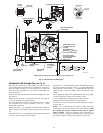
The condensate drain trap supplied with the furnace MUST be
used. The drain connection on the condensate drain trap is sized for
3
/
4
″ (19.1mm) PVC or CPVC pipe, however alternate
1
/
2
″
(12.7mm) CPVC [nominal
5
/
8
″ (15.9mm) O.D.] or vinyl tubing
with a minimum inner diameter (I.D.) of
5
/
8
″ (15.9mm) may also be
used, as allowed by local codes. Alternate drain pipes and hoses
maybeusedasallowedbylocalcodes.
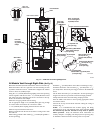
The drain line must maintain a
1
/
4
″ (6.4mm) per foot (304.8mm)
downward slope toward the drain.
1
/
4
″ (6.4mm) per foot
(304.8mm) is recommended. Installation of an overflow line is
recommended when the
1
/
4
″ (6.4mm) per foot (304.8mm) slope to
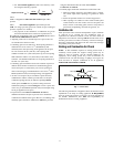
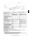
the condensate drain cannot be maintained. A drain tube clip is
included in the furnace to prevent kinking/buckling of the drain
tube. The clip should remain in the furnace (between the door
switch plate and the blower shelf, Fig. 10) during operation. See
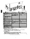
Fig. 20 for proper routing and installation of the overflow.
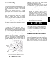
DrainTube
Clip
Door
Switch
Blower
Shelf
Representativedrawingonly,somemodels may vary in appearance.
A07705
Fig. 10 -- Drain Tube Clip Location
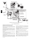
DO NOT trap the drain line i n any other location than at the
condensate drain trap supplied with the furnace.
If possible, DO NOT route the drain line where it may freeze. The
drain line must terminate at an inside drain to prevent freezing of
the condensate and possible property damage.
1. A condensate sump pump MUS T be used if required by
local codes, or if no indoor floor drain is available. The
condensate pump must be approved for use with acidic
condensate.
2. A plugged condensate drain line or a failed condensate
pump will allow condensate to spill. If the furnace is
installed where a condensate spill could cause damage, it is
recommended that an auxiliary safety switch be installed to
prevent operation of the equipment in the event of pump
failure or plugged drain line. If used, an auxiliary safety
switch should be installed in the R circuit (low voltage)
ONLY.
3. If the auxiliary switch in the condensate pump is used, the
furnace may shut down due to a blocked condensate line or
failed pump. To prevent frozen water pipes see the “Frozen
Water Pipe Hazard” section of this manual.
FROZEN AND BURST WATER PIPE HAZARD
Failure to follow this caution may result in property damage.
If a condensate pump is installed, a plugged condensate drain
or a failed pump may cause the furnace to shut down. Do not
leave the home unattended during freezing weather without
turning off water supply and draining water pipes or otherwise
protecting against the risk of frozen pipes.
CAUTION
!
Condensa te Drain Trap Freeze Protection
Special precautions MUST be made if installing furnace in an area
which may drop below freezing. This can cause improper operation
or damage to the equipment. If the the furnace environment has the
potential of freezing, the drain trap and drain line must be protected.
Use 3 to 6 watt per foot at 115 volt, 40° F(4°C) self--regulating
shielded and waterproof heat tape. Wrap the drain trap and drain
line with the heat tape and secure with the ties. Follow the heat tape
manufacturer’s recommendations. Prime the trap before furnace
operation.
58HDV