


29
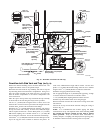
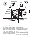
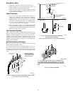
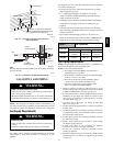
Using Exterior Risers
1. Install elbows and pipe to form riser as shown in Fig. 23
2. Secure vent pipe to wall with galvanized strap or other rust
resistant material to restrain pipe from moving.
3. Insulate pipe with Armaflex or equivalent moisture resistant
closed cell foam insulation or Fiberglass insulation if boxed
in and sealed against moisture.
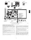
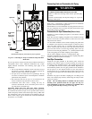
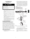
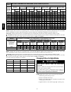
Vertical Termination
1. Fig. 25 shows the proper installation and clearances for
vertical vent termination. The vertical roof termination
should be sealed with a plumbing roof boot or equivalent
flashing. The inlet of the intake pipe and end of the exhaust
vent must be terminated no less than 12″ (307.8mm) above
the roof or snow accumulation level, and 12″ (307.8mm)
away from a vertical wall or other protrusion.
2. If the vent system is installed i n an existing chimney make
sure clearances shown in Fig. 25 a re maintained. Horizontal
section before the termination elbow can be extended on the
inlet air to provide necessary clearance.
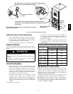
Vent Termination Shielding
Under certain wind conditions some building materials ma y be
affected by flue products expelled in close proximity to unprotected
surfaces. Sealing or shielding of the e xposed surfaces with a
corrosion resistant material (such as aluminum sheeting) may be
required to prevent staining or deterioration. The protective material
should be attached and sealed (if necessary) to the building before
attaching the vent terminal.
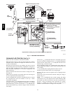
Multi Vent Termination Clearances
When two (2) or more furnaces are vented near each other, each
furnace must be individually vented.
Two (2) vent terminations may be installed as shown in Fig. 26, 27,
28, 29, and 30 but the next vent termination must be at least 36″
(914.4mm) away from first two terminations. It is important that
vent terminations be made as shown to avoid recirculation of flue
gases.
12 ” (304.8mm)
MIN.
8” (203.2mm)* MIN.
20’ (6.1m) MAX
25--00--04F
8” (203.2mm)
MIN.
GRADE LEVEL
SNOW LEVEL
OR
*18
″
(457.2mm) Minimum for
cold climates [sustained 0
_
F
(-17
_
C) and below for 24 or
more consecutive hours]
A07716
Fig. 23 -- Sidewall Termination with Exterior Risers to Get
Above Snow Level or Grade Level
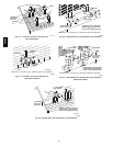
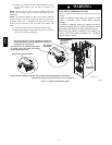
OVERHANG
12
″
(304.8mm) MIN. Ground
Level ORSnow Level
INLET
EXHAUST
90
°
Same Joist
Space
FRONT VIEW
SIDE VIEW
25-23-73
12
″
(304.8mm) MIN.
12
″
(304.8mm) MIN.
A07699
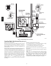
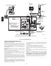
Fig. 24 -- Recommended Alternate Installation
for Sustained Cold Weather
(0_F(--17_C) & below for 24 or more consecutive hours)
2 5 -- 0 0 -- 0 6
A
A
B
A=12″ (304.8mm) Above roof or snow accumulation level
B=8″ (203.2mm) Min., 20′ (6.1m) Maximum, except in areas
with extreme cold temperatures [sustained 0°F(--17°C) and
below for 24 or more consecutive hours], the 18″ (457.2mm)
Min.
A07717
Fig. 25 -- Rooftop Termination
58HDV