


39
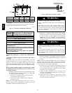
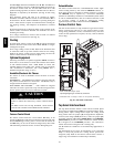
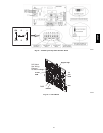
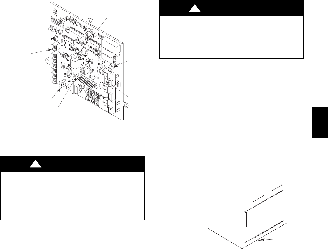
Dip Switch
See “Wiring
Diagram”
for switch settings
FUSE
115
VAC
HUM
DEHUM
Diagnostic Light
24 VAC
HUM
EAC
A07780
Fig. 41 -- Control Connections
DUCTWORK AND FILTER
CARBON MONOXIDE POISONING HAZARD
Failure to follow this warning could result in personal injury
or death.
Do NOT draw return air from inside a closet or utility room
where furnace is located. Return air duct MUST be sealed to
furnace casing.
!
WARNING
Installation
NOTE: Design and install the air distribution system to comply
with Air Conditioning Contractors of America manuals and/or
NFPA pamphlets 90A and 90B or other approved methods that
conform to local codes and good trade practices.
1. When furnace supply ducts carry air outside furnace area,
seal return air duct to furnace casing a nd terminate duct
outside furnace space.
2. Install air conditioning cooling coil (evaporator) on outlet
side of furnace.
3. For furnaces installed without a cooling coil, it is
recommended that the outlet duct be provided with a
removable access panel. This panel s hould be accessible
when the f urnace is installed so the exterior of the heat
exchanger can be viewed for inspections. The access panel
MUST be sealed to prevent leaks.
4. If separate evaporator and blower units are used, install good
sealing dampers for air flow control. Chilled air going
through the furnace could cause condensation and shorten
the furnace life.
NOTE: D ampers (field supplied) can be either automatic or
manual. Manually operated dampers MUST be equipped with a
means to prevent furnace or air conditioning operation unless
damper is in the full heat or cool position.
CARBON MONOXIDE POISONING HAZARD
Failure to follow this warning could result in personal injury
or death.
Cool air passing over heat exchanger can cause condensate to
form resulting in heat exchanger failure.
!
WARNING
Connections
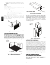
NOTE: Return air can enter through either side, both sides, the
botto m or a side and the bottom. Return air can not
enter through
rear of the furnace. When the furnace is located in an area near or
adjacent to the living a rea, the system should be carefully designed
with returns to minimize noise transmission through the return
grille. Any blower moving a high volume of air will produce
audible noise which could be objectionable to when the unit is
located very close to living areas. It is advisable to route the return
air ducts under the floor or through the attic.
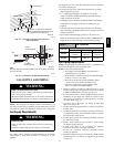
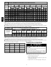
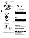
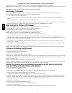
1. For side connections using a 16″ x25″ (406.4 x 635mm)
filter, cut out the embossed area shown in Fig. 42. This will
provide a 14
1
/
2
″ x22
1
/
2
″ (368.3 x 571.5mm) approximate
opening.
Embossed Area
on Side of Furnace
A
=14 /
2
″ (368.3mm)HeightofCutout for16″x25″(406.4x 635mm)Filter
B=22
1
/
2
″ (571.5mm)Width of Cutoutfor 16″ x25″ (406.4x 635mm) Filter
A
Furnace
Bottom
B
A07728
Fig. 42 -- Side Return Air Cutout
NOTE: Furnaces with 5 TONS cooling capacity may require
two(2) side returns or one side return with bottom return.
2. Bottom returns can be made by removing the knockout
panel in the furnace base. Do NOT remove knock-out
except for a bottom return.
3. Installation of locking-type dampers are recommended in all
branches, or in individual ducts to balance system’s air flow.
4. Non-combustible, flexible duct connectors are
recommended for return and supply connections to furnace.
5. If air return grille is located close to the fan inlet, install at
least one, 90° air turn between fan and inlet grille to reduce
noise.
NOTE: To further reduce noise, install acoustical air turning vanes
and/or line the inside of duct with acoustical material.
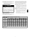
Sizing
Existing or new ductwork MUST be sized to handle the correct
amount of airflow for either heating only or heating and air
conditioning.
Insulation
1. Insulate ductwork installed in attics or other areas exposed to
outside temperatures with a minimum of 2″ (50.8mm)
insulation and vapor barrier.
58HDV