


19
Plastic Cap
Yellow or black
Vent Drain
&Clamps
INLET
EXHAUST
IN
ON
OFF
V
E
N
T
Casing Grommet
Black Rubber
5
/
8
″
(15.9mm) ID
(Loose partsbag)
Drain Connector Black PVC
3
/
4
″
(19.1mm) PVC X
1
/
2
″
(12.7mm) CPVC
(Loose parts bag)
Drain Tube
Corrugated
5
/
8
″
(15.9mm) ID
& Clamps
Coupling & Clamps
(Optional)
25 --24 --67a
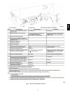
Single Pressure Switch
Dual Pressure Switch Detail
Tee Trap White PVC
(loose parts bag)
2
″
(50.8mm) PVC
Coupling
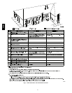
On Some Models
ONLY
Rotate downward
5
°
to 10
°
NOTE: Built--in channel will
be angled 5° to 10° also.
SIDE VIEW
Either: The PVC
Drain Tee or a field
supplied 2
″
(50.8mm) PVC Tee
AIR
FLOW
AIR
FLOW
Relief Tube
Black Rubber
3
/
16
″
(4.8mm) ID
Drain Tube
Black Rubber
1
/
2
″
(12.7mm) ID
&Clamps
Representative drawing only, some models may vary in appearance.
Drain Line Vent Tee
3
/
4
″
(18.1mm) PVC or
1
/
2
″
(12.7mm) CPVC (Field supplied)
A07707
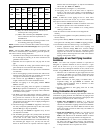
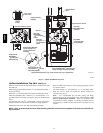
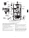
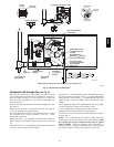
Fig. 12 -- Upflow Installa tions Vent through Left Side
Upflow Installations Vent through Left--Side (See Fig. 12)
Remove drain tee from inducer discharge and remove black drain
tube
1
/
2
″ (12.7mm) ID from bottom of drain tee.
Install Vent Pipe grommet in side of casing.
Cut an appropriate length of 2″ (50.8mm) PVC pipe long enough
to exit the cabinet and connect the vent drain to either:
S A2″ (50.8mm) PVC coupling fastened onto the drain tee
Install tee trap into bottom of tee.
Remove knockout from the side of the furnace casing where drain
tube will exit.
Install the
1
/
2
″ (12.7mm) CPVC street elbow on discharge of trap
Install the black PVC drain connector [
3
/
4
″ (19.1mm) PVC x
1
/
2
″
CPVC from loose parts bag] as shown in the illustration above.
Cut the black drain tube [
5
/
8
″ (15.9mm) ID -- in loose parts bag] to
length to fit between trap and tube connector through grommet.
Clamp both ends of the drain tube using clamps provided.
Glue the CPVC street elbow to the trap using appropriate cleaner
and solvent cement.
Connect the tee trap and the main drain line exiting t he casing as
showninFig.12
Note: It is recommended that all PVC piping and fitting
connections be fit up and inspected before final cementing. Both
the internal trap and the external tee trap must be primed
before operation. Verify all condensate drain connections are
securely clamped. A c oupling a nd clamps (in loose part bag) may
be installed as shown for future servicing of the vent system.
58HDV