


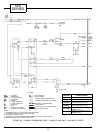
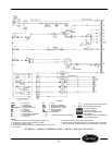

LEGEND
CAP — Capacitor
COMP — Compressor
CR — Cooling Relay
EQUIP GND — Equipment Ground
FM — Fan Motor
FR — Fan Relay
HR — Heating Relay
IFT — Indoor Frost Thermostat
L—Power Supply Line
OFT — Outdoor Frost Thermostat
OL — Overload
PL — Plug
PLS — Primary Limit Switch
RVR — Reversing Valve Relay
RVS — Reversing Valve Solenoid
SLS — Secondary Limit Switch
SSS — Speed Selector Switch
ST — Start Thermistor
TB — Terminal Board
TRANS — Transformer
Component Connection (Marked)
Component Connection (Unmarked)
Terminal Board Connection
Field Control Wiring
Accessory or Optional Wiring
Factory Wiring
To Indicate Common Potential Only.
Not to Represent Wire
NOTES:
1. Recommended for use on grounded power supply only.
2. Compressor and fan motor thermally protected.
3. Use copper conductors only.
4. All wiring must conform with NEC (National Electrical Code) and lo-
cal codes.
5. Dashed lines indicate components when used.
6. Control center use thermostat part no. HH01AD045 or equivalent.
7. Field control wire suitable for NEC class 2 control circuit, at 24 volts.
FIGURE 87 — WIRING SCHEMATIC; 52SQ — 208/230 V AND 265 V RC UNITS
55