


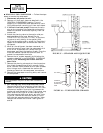
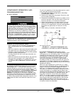
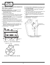
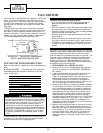
Ⅲ INDOOR THERMOSTAT (Heat Pump Units) (cont)
(Figure 54) — To verify operation of the heat pump in-
door thermostat switch, a continuity test may be per-
formed as follows:
1. Turn off unit power as described in GENERAL
DISASSEMBLY section.
2. Remove wire leads from thermostat. Note their loca-
tions to ease re-assembly.
3. To test stage A, place one lead of the continuity
tester on the terminal marked 2, and the other lead
on either the terminal marked 1 or the terminal
marked 3.
4. Adjust the thermostat up or down to verify the con-
tacts of the switch open and close. When verifying
continuity of the closed switch, the reading on the
meter should be 0 ohms. An open switch will show OL
on the meter.
5. To test stage B contacts, place one lead of the conti-
nuity tester on contact 5 and the other lead on either
contact 4 or contact 6.
6. Adjust the thermostat up or down to verify the con-
tacts of the switch open and close as in Step 4.
7. When testing is complete, reconnect the leads.
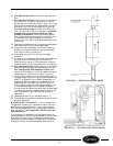
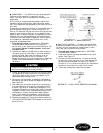
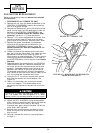
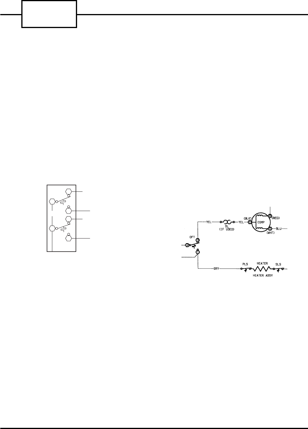
Ⅲ OUTDOOR FROST THERMOSTAT (Heat Pump Units)
(Figure 55) — The Outdoor Frost Thermostat (OFT) is
a thermostat that uses a single-pole switch with a
manual override selector. The thermostat switches be-
tween electric heat and compressor operation when the
temperature of the outdoor coil falls below 15 F or
rises above 35 F. Switching the override selector to elec-
tric heat disables the reverse cycle operation of the
thermostat is manually switched to electric heat opera-
tion, the compressor is disabled for heating and cool-
ing operations.
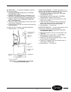
To verify the OFT is operational, a continuity test may
be performed as follows:
1. Turn off unit power as described in GENERAL
DISASSEMBLY section.
2. Remove the leads from the OFT. Note their locations
to ease re-assembly.
3. Connect the continuity tester to the switch terminals
marked 1 and 2.
4. Rotate the override switch to the electric heat setting
and verify that there is continuity between termi-
nals 1 and 2.
5. To check the other contacts, move the lead on termi-
nal 1 to terminal 3. Rotate the override switch to the
heat pump setting. There should now be continuity
between terminals 2 and 3.
6. Once the test is complete, reconnect the leads.
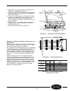
LEGEND (Figures 53 - 55)
COMP — Compressor
FCS — Fan Control Switch
IT — Indoor Thermostat
OFT — Outdoor Frost Thermostat
OL — Overload
PLS — Primary Limit Switch
SLS — Secondary Limit Switch
TBH — Thermostat Bulb Heater
ORN
BLK
BLU
GRY
BRN
IT
2
1
3
4
6
5
FIGURE 54 — INDOOR THERMOSTAT (IT)
CONTACTS, ALL 52SQ AA AND CP MODELS
FIGURE 55 — OUTDOOR FROST THERMOSTAT (OFT)
CONTACTS, ALL 52SQ AA AND CP MODELS
52S
SERIES
28