


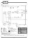
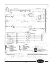

LEGEND
CAP — Capacitor
COMP — Compressor
FCS — Fan Cycle Switch
FM — Fan Motor
HTR — Heater
IT — Indoor Thermostat
L—Power Supply Line
OL — Overload
PL — Plug
PLS — Primary Limit Switch
RVS — Reversing Valve Solenoid
SLS — Secondary Limit Switch
ST — Start Thermistor
SW — Switch
Component Connection (Marked)
Component Connection (Unmarked)
Accessory or Optional Wiring
Factory Wiring
To Indicate Common Potential Only.
Not to Represent Wire
NOTES:
1. Recommended for use on grounded power supply only.
2. Compressor and fan motor thermally protected.
3. Use copper conductors only.
4. All wiring must conform with NEC (National Electrical Code) and local codes.
5. Dashed lines indicate components when used.
FIGURE 86 — WIRING SCHEMATIC; 52SQ — 208/230 V AND 265 V AA AND CP UNITS
SWITCH
POSITION
CONTACTS MADE
OFF NONE
FAN L1 TO LO*
LO HEAT L1 TO IT1, FCS TO LO, L2 TO HTR
HI HEAT L1 TO IT1, FCS TO HI, L2 TO HTR
LO COOL L1 TO IT3, FCS TO LO
HI COOL L1 TO IT3, FCS TO HI
*L1 to MED, some models.
52S
SERIES
54