


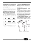
Ⅲ CAPACITOR — The 52S units use a dual capacitor.
One part of the capacitor is used with the fan
motor. The other part of the capacitor is used by the
compressor.
Run circuits on single-phase compressor motors use
capacitors which dramatically affect the motor opera-
tion. Run capacitors are connected to the motor circuit at
all times.
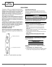
To evaluate the capacitor, perform a visual check first. A
shorted capacitor may give a visual indication of its
failure. For example, the pop-out hole at the top of a start
capacitor may bulge or blow out. A run capacitor may
bulge or leak. In these instances, the capacitor must be
replaced with one recommended by the manufacturer.
If there are no visual signs of capacitor failure, testing
of the capacitor resistance may be done with a volt-
ohmmeter as detailed below:
1. Turn off unit power as described in GENERAL
DISASSEMBLY section but do not unplug the
service cord; it will supply ground connection for the
unit chassis. Check to ensure power is off and
LOCKED OUT.
2. Connect one lead of a 20,000 ohm, 2-watt resistor to
the center group of terminals on the dual capacitor.
Attach the other lead from the resistor to an un-
painted metal section of the unit chassis. This
allows that section of the dual capacitor to discharge.
Repeat this process between the other group of
terminals.
Capacitors are capable of holding charge similar to a
battery and may cause an electrical shock.
3. Locate and disconnect the wires from the start and/or
run capacitor to isolate them from the remainder of
the circuit. Refer to the unit wiring diagram if you
need assistance locating wires.
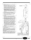
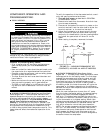
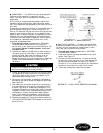
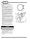
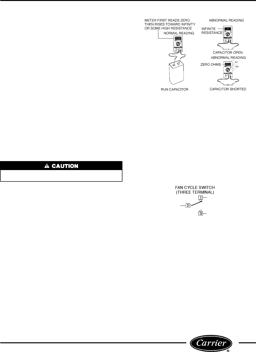
4. Set up the volt-ohmmeter to measure resistance by
connecting the meter across the capacitor terminals.
See Figure 56.
5. The reading on the meter should first indicate zero,
or a low resistance, then slowly rise toward infinity
or some high value or measurable resistance. This
indicates the capacitor is most likely good. If the read-
ing goes to zero or a low resistance and stays there,
the capacitor is likely shorted and needs replace-
ment. If the reading immediately indicates infinity,
the capacitor is likely open and must be replaced.
6. Replace the capacitor if failed and rewire according
to the WIRING SCHEMATICS located in the control
box of the unit.
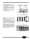
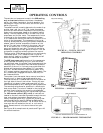
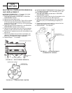
Ⅲ FAN CYCLE SWITCH — The fan cycle switch has
2 operating modes, continuous (CON) and cycle (CYC).
To verify the fan cycle switch is operational, a conti-
nuity test may be performed as follows:
1. Turn off unit power as described in GENERAL
DISASSEMBLY section.
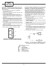
2. Label and remove the leads connected to fan cycle
switch. See Figure 57.
3. Connect the volt-ohmmeter for 1X ohms and check
for continuity from terminal 2 to 1 then change the
switch position and check for continuity from ter-
minal 2 to 3. For a 6-terminal switch this test should
be done on terminals 5 to 4 and 5 to 6 as well.
4. Once test is complete, reconnect the leads.
FIGURE 56 — CAPACITOR TEST
FIGURE 57 — FAN CYCLE SWITCH (3 Terminal)
29