


ELECTRICAL COMPONENTS REMOVAL
AND REPLACEMENT
Ⅲ INDOOR THERMOSTAT — To remove the indoor
thermostat, perform the following steps:
1. Turn off unit power as described in GENERAL
DISASSEMBLY section.
2. Remove the thermostat knob.
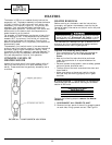
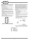
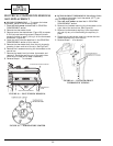
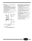
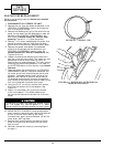
3. Remove control box escutcheon (Figure 58) to expose
2 Phillips head mounting screws. Remove the tem-
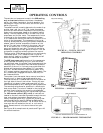
perature limiter by gently lifting it off the thermostat
knob shaft (Figure 59).
4. Open the control box as described in the GENERAL
DISASSEMBLY section of this manual.
5. Remove the thermostat bulb from the clip by gently
pressing it down and out of the clip. See Figure 27.
6. Remove the 2 screws mounting the thermostat to the
control box.
7. Remove the leads from the indoor thermostat and
remove it. Route the capillary out of the control box.
Note the wire locations to ease re-assembly.
8. Reverse Steps1-7toreinstall.
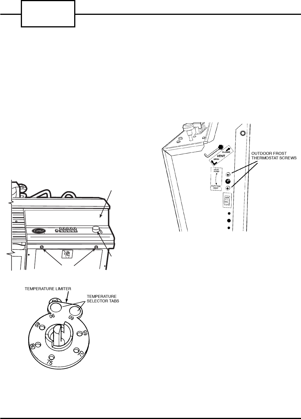
Ⅲ OUTDOOR FROST THERMOSTAT (Heat Pump Units)
— To remove the outdoor frost thermostat (OFT), per-
form the following steps:
1. Turn off unit power as described in GENERAL
DISASSEMBLY section.
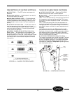
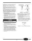
2. Remove the 2 screws mounting the thermostat to the
right side of the control box. See Figure 60.
3. Remove the thermostat capillary from the outdoor
coil and clip any wire ties holding the capillary in
place.
4. Disconnect the wires and carefully remove the ther-
mostat and capillary from the unit.
5. Reverse Steps1-4toreinstall.
CONTROL BOX ESCUTCHEON
THERMOSTAT
KNOB
ESCUTCHEON SCREWS
FIGURE 58 — ESCUTCHEON REMOVAL
FIGURE 59 — TEMPERATURE LIMITER
FIGURE 60 — OUTDOOR FROST
THERMOSTAT SCREWS
52S
SERIES
30