


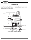
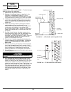
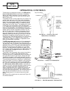
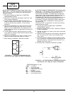
OPERATING CONTROLS
The controls and components used in the 52S cooling
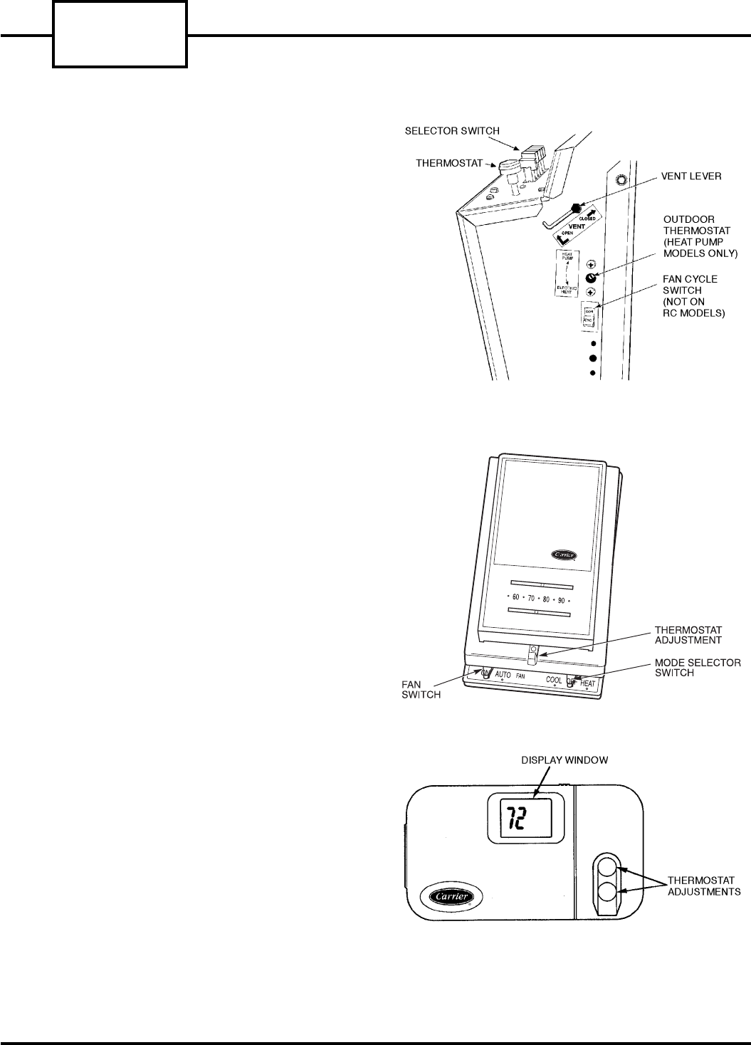
only or heat/cool units are as follows: the selector
switch, the indoor thermostat, the dual capacitor, the
temperature limiter, the vent lever, and the fan cycle
switch (Figure 45).
The selector switch is used to determine the mode of op-
eration: heat, cool, fan, or off. The indoor thermostat
controls the room ambient temperature and cycles the
heater or the compressor based on the selector switch
setting. The dual capacitor aids in the start-up of the
compressor and the fan motor. The temperature limiter
is mounted on the thermostat under the escutcheon.
It is a mechanical device that restricts the amount of ro-
tation of the thermostat. The temperature limiter de-
vice may be adjusted by moving the plastic temperature
selector tabs to another temperature location on the
device. The vent lever is located in the upper right cor-
ner of the control box. It is a slide mechanism that
opens and closes the vent door. The control may be ac-
cessed by removing the front panel of the unit. The fan
cycle switch is used to provide 2 options of fan control.
The first option, CON, causes the fan to run continuously.
The second option, CYC, causes the fan to cycle on
when venting, heating, or cooling is requested and off
when the thermostat is satisfied.
The 52S heat pump unit contains all the components
of the heat/cool and cooling only unit, and the follow-
ing additional ones: the outdoor frost thermostat and the
reversing valve. The outdoor frost thermostat prevents
operation of the unit in the heat pump mode when the
outdoor coil temperature drops below 15 F, or at about
30 to 35 F outdoor ambient temperature (about 40 to
45 F outdoor ambient temperature for 1999 models). The
unit automatically engages the electric heat strip un-
der these conditions.
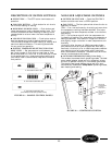
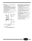
The outdoor frost thermostat has a manual override to
place the unit in electric heat mode operation only.
The override switch is located behind the front panel on
the right side of the unit control box. Placing the over-
ride switch into electric heat mode operation will dis-
able the compressor for ALL heating or cooling operations.
The reversing valve allows for operation in reverse cycle
heat pump mode. The valve is located in the piping sys-
tem and is controlled by the reversing valve solenoid
coil. The coil is energized only during the heating mode.
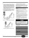
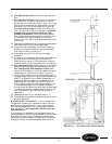
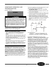
For 52S remote control (RC) units, all controls are
located on the wall mounted thermostat except the vent
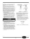
lever and outdoor thermostat. Remote control is a
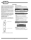
factory-installed option only. There are 2 styles of ther-
mostats qualified for use with 52S series Remote Con-
trol units. See Figures 46 and 47. For all other 52S units,
room controls are located on the unit or unit control
panel. Remote control units do not have a fan cycle
switch.
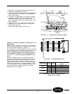
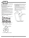
See Figure 48 for sample control panels and Figure 49
for controls locations.
FIGURE 45 — TYPICAL 52S UNIT
OPERATING CONTROLS
FIGURE 46 — MANUAL THERMOSTAT
RCD P/N TSTATCCPAC01-A or TSTATCCPHP01-A
FIGURE 47 — PROGRAMMABLE THERMOSTAT
52S
SERIES
24