


3. Remove the unit from the sleeve as detailed in the
GENERAL DISASSEMBLY section.
4. Remove the discharge air grille and the discharge air
deck as detailed in the GENERAL DISASSEMBLY
section. Save screws.
5. Once the air discharge deck is removed, the heater
assembly is exposed. After noting positions of wires
and labelling them, use a pair of needle nose
pliers to carefully remove the wires connected to the
heater assembly.
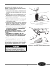
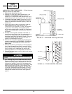
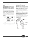
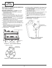
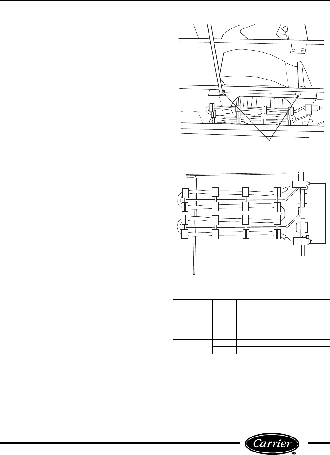
6. Remove the two
1
⁄
4
-in. screws mounting the heater
assembly to the inside of the partition. Save the
screws. See Figure 42.
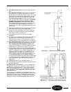
7. Remove the heater assembly (Figure 43).
Examine the heater as follows to determine if it is
operational:
Perform a visual inspection. The heater coil should be
free of breaks. If there are any breaks in the coil, replace-
ment of the heater assembly is necessary.
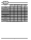
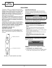
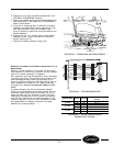
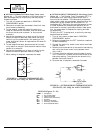
Coil resistance must also be checked to verify the heater
is operating correctly. The resistance of the heater coils
must meet approximate levels for the heater to per-
form at its optimum efficiency. See Figure 44 for approxi-
mate resistance for heaters at 75 F. Before checking
the heater coil resistance, be sure all power to unit
is off.
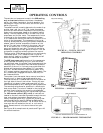
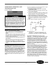
To check resistance, set the volt-ohmmeter selector
switch to the lowest ohms value. Next connect the volt-
ohmmeter leads to each side of the heater coil at the
studs that hold the limit switches in place. Incorrect
readings can be obtained if the wires are not removed
from the limit switches on the heater assembly. If the
resistive reading is infinite or zero, the heater is failed
and replacement is necessary. Reinstall the heater
assembly by reversing steps1-7.
SCREWS (2)
FIGURE 42 — REMOVING HEATER SCREWS
FIGURE 43 — HEATER REMOVED
HEATER SIZE WATTS VOLTS
ACCEPTABLE RESISTANCE
(Ohms)
2.3 kW
2300 230 20 - 23
2300 265 28 - 31
3.4 kW
3400 230 13 - 16
3400 265 19 - 21
5.0 kW
5000 230 9 - 11
5000 265 13 - 15
FIGURE 44 — ACCEPTABLE HEATER
RESISTANCE VALUES
23