


DESCRIPTION OF SWITCH SETTINGS
Ⅲ OFF BUTTON — The OFF button terminates unit
operation.
Ⅲ FAN ONLY BUTTON — Push button for air circula-
tion without heating or cooling.
Ⅲ HIGH HEAT OR HIGH COOL — Push button and
rotate temperature knob to desired comfort level. This
function provides maximum heating or cooling, and is
recommended to raise or lower the room temperature
quickly.
Ⅲ LOW HEAT OR LOW COOL — Push button and ro-
tate the temperature knob to desired comfort level.
This function provides minimum heating or cooling with
maximum dehumidification. This setting also allows
for very quiet fan operation.
Ⅲ FINDING TEMPERATURE SETTING FOR COM-
FORT LEVEL — Set temperature knob between num-
ber 5 and number 6. Push High or Low Heat or Cool
button and allow unit to run for 15 to 30 minutes. If room
is not comfortable, turn knob one number setting at a
time. When room is comfortable, keep control knob at
that position.
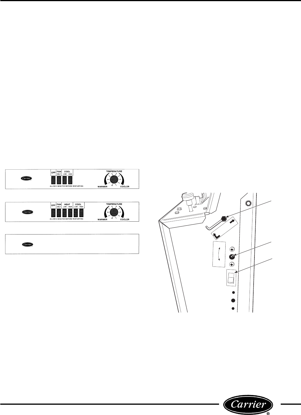
NON-USER ADJUSTABLE SWITCHES
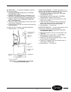
Ⅲ OUTSIDE OR VENT AIR — Push the FAN ONLY
button and slide vent lever to OPEN position.
Ⅲ FAN CYCLE — The fan cycle switch allows the fan to
operate in 2 modes:
CON — Fan runs continuously, circulating air even when
the temperature setting has been satisfied. This helps
to maintain the room temperature closer to the thermo-
stat setting.
CYC —Fan cycles on and off with the compressor dur-
ing heating or cooling. Fan stops when the temperature
setting is satisfied. This results in longer unit off-time
and slightly larger variations in room temperature and
humidity.
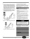
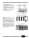
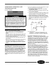
Units built after the start of 1996 incorporate single-
pole, double-throw fan cycle switches that have only 3
terminals. Units built prior to 1996 incorporate a double-
pole, double-throw fan cycle switch with 6 terminals
and a thermostat bulb heater. The additional terminals
control the thermostat bulb heater.
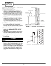
Ⅲ OUTDOOR THERMOSTAT (52SQ Units Only) —
The outdoor thermostat has 2 operating modes. The heat
pump mode (selector screw set fully clockwise), allows
the unit to operate normally in the reverse cycle mode.
The electric heat mode (selector screw set fully coun-
terclockwise), disables all compressor operating modes,
both heating and cooling.
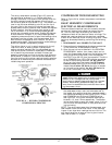
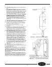
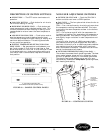
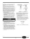
C. 52S COOLING/HEATING UNIT
WITH REMOTE CONTROL (BLANK PLATE)
FIGURE 48 — SAMPLE CONTROL PANELS
A. 52S COOLING ONLY UNIT
B. 52S COOLING/HEATING UNIT
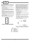
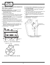
HEAT
PUMP
ELECTRIC
HEAT
VENT
CLOSED
OPEN
CON
CYC
OUTDOOR
THERMOSTAT
(ON HEAT
PUMP ONLY)
FAN CYCLE
SWITCH
(NOT ON RC
UNITS)
VENT
LEVER
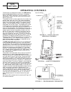
FIGURE 49 — CONTROLS LOCATION
25