


4
PREINSTALLATION
1. Check items received against packing list. Notify Carrier
of any discrepancy.
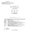
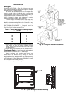
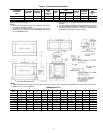
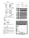
2. Refer to Fig. 4 for service area requirements.
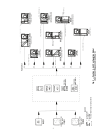
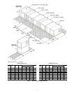
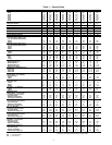
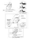
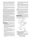
3. To transfer unit from truck to storage site, refer to rigging
details in Fig. 5 and section on unit rigging for proper
handling. See Table 1 for component weights.
4. Do not stack unit components or accessories during stor-
age. Stacking can cause damage or deformation.
5. If unit is to be stored for more than 2 weeks prior to in-
stallation, observe the following precautions:
a. Choose a dry storage site that is reasonably level
and sturdy to prevent undue stress or permanent
damage to the unit structure or components. Do not
store unit on vibrating surface. Damage to station-
ary bearings can occur. Set unit off ground if in
heavy rain area.
b. Remove all fasteners and other small parts from
jobsite to minimize theft. Tag and store parts in a
safe place until needed.
c. Cover entire unit with a tarp or plastic coverall.
Extend cover under unit if stored on ground.
Secure cover with adequate tiedowns or store
indoors. Be sure all coil connections have protec-
tive shipping caps.
d. Monthly — Remove tarp from unit, enter fan
section through access door or through fan inlet,
and rotate fan and motor slowly by hand to redis-
tribute the bearing grease and to prevent bearing
corrosion.
Rigging (Fig. 5) — All 39L units can be rigged by means
of the lifting brackets on bottom of unit.
Units are shipped fully assembled. Do not remove shipping
skids or protective covering until unit is ready for final place-
ment. Use slings and spreader bars as applicable to lift unit. Do
not lift unit by coil connections or headers.
Do not remove protective caps from coil piping connections
until ready to connect piping.
Do not remove protective cover or grease from fan shaft un-
til ready to install sheave.
Lay rigid temporary protection such as plywood walkways
in unit to prevent damage to insulation or bottom panel during
installation.
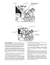
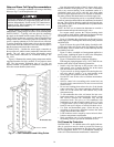
Suspended Units — Figure 6 shows overhead suspen-
sion of unit using optional factory-supplied suspension
channels.
Each support channel consists of 2 pieces, the smaller of
which fits inside the larger one. This allows the channel to be
adjusted to the required length for installation.
Channels are shipped on top of the unit. The 2 sections of
each channel are shipped one inside the other, and are held in
place during shipping by the panel screws in the top panel.
Hardware required for installation of suspension channels is
shipped in a package inside the fan section.
At least 2 suspension channels are shipped with each fan
and coil unit. One or more extra channels will be supplied
depending on the number of accessories ordered. Be sure to
install all the suspension channels shipped with a unit. Refer to
39L Isolator Mounting (Suspended Unit) certified drawing for
details.
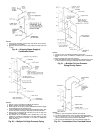
To install suspension channels:
1. Remove panel screws to free suspension channels for in-
stallation. Replace screws in top panel.
2. Adjust channel to required length by sliding one channel
section inside the other. The channel must extend at least
9 in. but not more than 12 in. beyond the edge of the unit.
Set length of channel by installing factory-supplied bolts
through the overlapping channel sections.
3. Mount unit to suspension channel using factory-supplied
nuts and bolts through
7
/
16
-in. diameter holes in unit lift-
ing bracket.
4. Install field-supplied suspension rods through
9
/
16
-in. di-
ameter holes provided at outer edges of channel. Be sure
hanger rods are securely fastened in place.
Service Clearance — Provide adequate space for unit
service access (fan shaft and coil removal, filter removal, mo-
tor access, damper linkage access, etc.) as shown in Fig. 4.
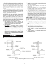
Condensate Drain — To prevent excessive build-up of
condensate in drain pan, adequate trap clearance must be pro-
vided beneath the unit as indicated in Fig. 7. See Installation,
Condensate Drain section (page 8) for additional details.
External Vibration Isolators — Install vibration iso-
lators per certified drawings, and in accordance with the job
specifications and the instructions of the vibration isolator
manufacturer. The coil piping must be isolated or have a flexi-
ble connection to avoid coil header damage because of unit
motion. A flexible connection should be installed at the fan dis-
charge.
Figure 6 shows isolation location for floor mounting or
overhead suspension of unit.
If a fork lift truck is used, lift only from heavy end of skid.
Minimum recommended fork length is 48 inches.