


31
6. If solution is too weak, add more antifreeze until desired
strength is reached, then circulate solution through coil
for 15 minutes or until concentration is satisfactory.
7. Remove upper line from reservoir to reversible pump.
Drain coil to reservoir and then close service valve.
8. Break union and remove reservoir and its lines.
9. Leave coil flanges or coupling open and auxiliary drain
valves open until spring.
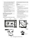
AIR DRYING METHOD OF COIL PROTECTION (Unit
and coil must be level for this method.)
1. Close coil water supply and return main valves.
2. Drain coil as described in procedures for Antifreeze
Methods of Coil Protection.
3. Connect air supply or air blower to inlet header connec-
tion and close its drain connection.
4. Circulate air and check for air dryness by holding mirror
in front of open vent in outlet header drain connection.
Mirror will fog if water is still present.
5. Allow coil to stand for a few minutes; repeat step 4 until
coil is dry.
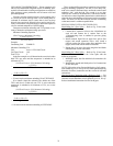
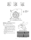
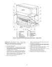
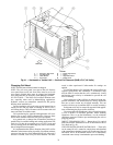
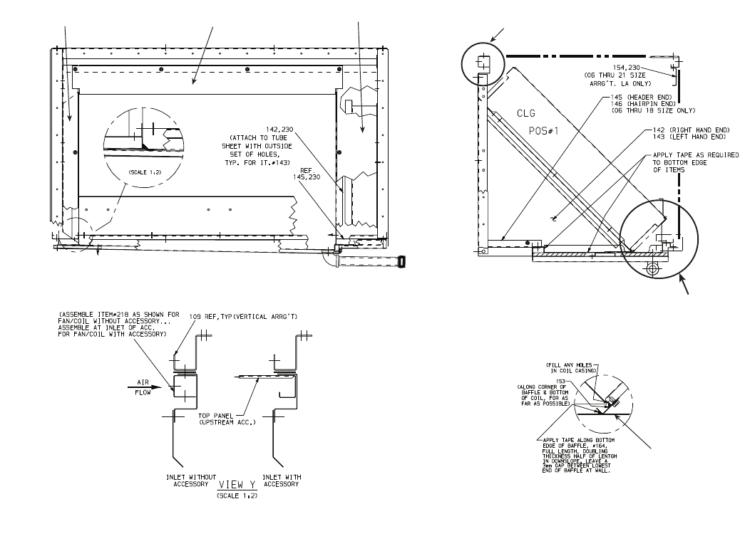
Field-Installed Coils (39LA,LD Only)
When a 39LA or 39LD unit is ordered without the coil, the fol-
lowing loose parts are shipped: (see Fig. 37)
• bottom coil baffle
• side hairpin baffle
• side header baffle
• top coil baffle
These parts should be field-installed onto the coil before
placing the coil into the unit. Once the baffles are installed,
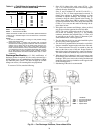
install the coil with the downstream bottom of the coil attached
to the upright mounting flange as shown in Fig. 36. Adjust
the coil and then attach the top coil baffle to the top flange
provided.
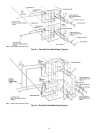
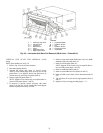
Coil Removal
HORIZONTAL UNIT SLANT COIL REMOVAL (39LA
Units)
NOTE: Item numbers are in Fig. 38.
1. Refer to Fig. 4 for service area clearance.
2. Disconnect piping (Item 5).
3. On top panel (Item 3), remove screws located directly
above side panels (Items 2 and 6). Top panels may be re-
moved from unit to provide more workspace, but it is not
required.
4. Remove right side panels (Item 6).
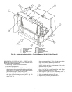
5. If accessory is present, remove accessory side panel
(Item 1) on left side of unit. Detach filter track support
bracket if upstream accessory is a filter.
6. Remove screws from inside baffle (Item 13). Leave baffle
attached to left side panel (Item 2).
7. Remove left side panel (Item 2).
8. Remove condensate baffle (Item 8).
9. Remove coil holddown screws (Items 9 and 11).
10. Remove baffle screws (Item 4) from downstream side of
coil.
11. Tilt coil (Item 10) away from coil support panels (Items 7
and 12) and slowly slide coil out of unit.
12. Replace coil by reversing preceding Steps 1-11.
BOTTOM COIL
BAFFLE
SEE TOP
FLANGE DETAIL
BOTTOM
MOUNTING
FLANGE
TOP FLANGE DETAIL
TOP COIL
BAFFLE
SIDE HEADER
BAFLE
SIDE HAIRPIN
BAFFLE
Fig. 37 — Field-Installed Coils (39LA and LD only)