


14
Water and Steam Coil Piping Recommendations
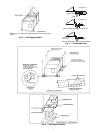
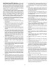
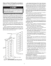
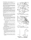
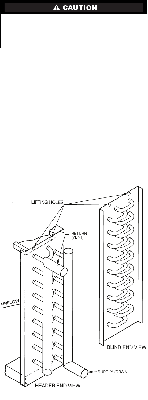
GENERAL — Use straps around the coil casing or the lifting
holes (see Fig. 17) to lift and place the coil.
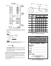
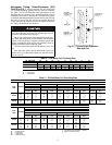
Piping practices are outlined in the Carrier System Design
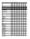
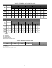
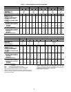
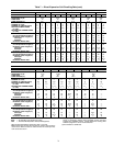
Manual, Part 3, Piping Design. See Tables 4-6 for circuiting data.
WATER COILS — Typically, coils are piped by connecting
the supply at the bottom and the return at the top. See Fig. 17.
This is not always the case, especially if the coil hand has been
changed in the field. Coils must be piped for counterflow; oth-
erwise, a capacity reduction of 5% for each coil row will result.
To ensure counterflow, chilled water coils are piped so that the
coldest water meets the coldest air. Hot water coils are piped so
that the warmest water meets the warmest air.
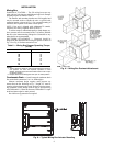
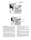
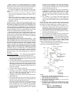
STEAM COILS — Position the steam supply connection at
the top of the coil, and the return (condensate) connection at the
bottom. The coil tubes must incline downwards toward
the return header connection for condensate drainage. See
Fig. 18-22.
Figure 18 illustrates the normal piping components and the
suggested locations for high, medium, or low-pressure steam
coils. The low-pressure application (zero to 15 psig) can
dispense with the ¼-in. petcock for continuous venting located
above the vacuum breaker (check valve).
Note the horizontal location of the 15-degree check valve,
and the orientation of the gate/pivot. This valve is intended to
relieve any vacuum forming in the condensate outlet of a
condensing steam coil, and to seal this port when steam
pressure is again supplied to the coil. It must not be installed in
any other position, and should not be used in the supply line.
For coils used in tempering service, or to preheat outside air,
install an immersion thermostat in the condensate line ahead of
the trap. This will shut down the supply fan and close the out-
door damper whenever the condensate falls to a predetermined
point, perhaps 120 F.
NOTE: Do NOT use an immersion thermostat to override a
duct thermostat and open the steam supply valve.
For vacuum return systems, the vacuum breaking check
valve would be piped into the condensate line between the trap
and the gate valve instead of open to the atmosphere.
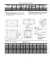
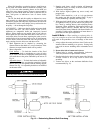
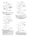
Figure 19 illustrates the typical piping at the end of every
steam supply main. Omitting this causes many field problems
and failed coils.
Figure 20 shows the typical field piping of multiple coils.
Use this only if the coils are the same size and have the same
pressure drop. If this is not the case, an individual trap must be
provided for each coil.
Figure 21 shows a multiple coil arrangement applied to a
gravity return, including the open air relief to the atmosphere,
which DOES NOT replace the vacuum breakers.
Figure 22 illustrates the basic condensate lift piping.
Following the piping diagrams in Fig. 18-22, make all con-
nections while observing the following precautions:
• Install a drip line and trap on the pressure side of the
inlet control valve. Connect the drip line to the return
line downstream of the return line trap.
• To prevent scale or foreign matter from entering the con-
trol valve and coil, install a
3
/
32
-in. mesh strainer in the
steam supply line upstream from the control valve.
• Provide air vents for the coils to eliminate noncondens-
able gases.
• Select a control valve according to the steam load, not
the coils supply connection size. Do not use an oversized
control valve.
• Do not use bushings that reduce the size of the header
return connection. The return connection should be the
same size as the return line and reduced only at the
downstream trap.
• To lift condensate above the coil return line into over-
head steam mains, or pressurized mains, install a pump
and receiver between the condensate trap and the
pressurized main. Do not try to lift condensate with
modulating or on-and-off steam control valves. Use only
15-degree check valves, as they open with a lower water
head. Do not use 45-degree or vertical-lift check valves.
• Use float and thermostatic traps. Select the trap size
according to the pressure difference between the steam
supply main and the return main.
• Load variations can be caused by uneven inlet air distri-
bution or temperature stratification.
• Drain condensate out of coils completely at the end of
the heating season to prevent the formation of acid.
Coil Freeze-Up Protection
WATER COILS — If a chilled water coil is applied with out-
side air, provisions must be made to prevent coil freeze-up.
Install a coil freeze-up thermostat to shut down the system if
any air temperature below 36 F is encountered entering the
water coil. Follow thermostat manufacturer’s instructions.
To prevent damage to the coil or coil headers: Do not use
the headers to lift the coil. Support the piping and coil con-
nections independently. Do not use the coil connections to
support piping. When tightening coil connections, use a
backup wrench on the nozzles.
Fig. 17 — Coil Connections and Lifting Points