


10
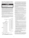
Inlet Guide Vane (IGV) Actuators — The control
board positions the unit IGVs in order to maintain the duct stat-
ic pressure, as measured by the static pressure transducer, at the
required set point. The IGV actuator is electrically connected to
the control board and receives a signal whenever the guide
vane position needs to be adjusted. The guide vane actuator is
mounted to the IGV jackshaft, and secured to the jackshaft
mounting member in order to prevent rotation.
For factory-installed controls which are ordered with the
unit, the IGV actuator is properly sized and factory mounted to
the IGV jackshaft. The actuator wiring is routed across the fan
section to a junction box which is mounted to the exterior of
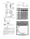
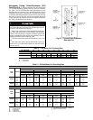
the unit. Two compatible actuators are available for field
installation. Both actuators are supplied with a length of
plenum rated cable to facilitate installation inside the unit. See
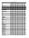
Table 3 for actuator specifications and typical applications.
Jackshaft and IGV linkage setup adjustments are extremely
important for proper IGV performance and static pressure con-
trol. Closely follow all instructions.
To install the IGV actuators, perform the following:
1. Disconnect power to the fan motor prior to performing
the installation.
2. Open the fan access door and locate the IGV jackshaft.
Measure the IGV jackshaft diameter. Verify that the size
is within the range of the actuator chosen. See Table 3.
3. Loosen the U-bolt locking nuts on the actuator.
4. Slip the actuator over the IGV jackshaft. Align the actua-
tor parallel with the frame member which supports the
jackshaft.
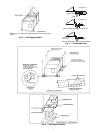
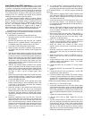
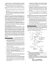
5. Take the anti-rotation bracket supplied with the actuator
and, with the center locking pin pointed outward, slip the
pin into the slot at the far end of the actuator. Seat the pin
into the center of the groove provided. If the anti-rotation
bracket is not seated against the frame member, measure
the distance from the member and remove the anti-
rotation bracket from the actuator. Bend the bracket to the
required offset. See Fig. 11.
6. With the anti-rotation bracket installed in the actuator
groove, locate the hole in the bracket, closest to the pin,
which is fully in contact against the frame. Mark this hole
location on the frame. Trace the outline of the bracket on
the frame so that it can be re-aligned again when
removed.
7. Remove the bracket and actuator. Drill a pilot hole at the
location marked from Step 6. Install one screw through
the hole. Re-align the bracket with the outline made pre-
viously and tighten the screw.
8. Locate and mark the hole on the opposite end of the
bracket, closest to the pin, which contacts the frame. Drill
a pilot hole in this location and install the remaining
screw. Remove the first screw.
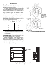
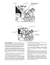
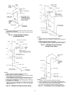
9. Install the actuator on the jackshaft and while moving
into position, adjust the free end of the anti-rotation
bracket so that the pin fully locks into the slot provided in
the actuator. Once the actuator is adjusted into position,
install the remaining screw into the anti-rotation bracket.
See Fig. 12.
10. Rotate the jackshaft to fully close the IGVs. Press the
release button (BLACK) on the face of the actuator, and
rotate the clamp in the same direction that closed the
IGVs, until the actuator stop is reached. With the release
still pressed, rotate the actuator clamp from the full closed
position to the .1 mark and release the actuator release
button. Lock the U-bolt clamp into position to secure the
actuator to the IGV jackshaft.
11. If a second actuator is required, repeat the process for a
second actuator. The second actuator mounts on the op-
posite side of the fan on the opposite end of the jackshaft.
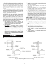
ACTUATOR WIRING — To wire the actuator, perform the
following:
1. Each actuator is supplied with a length of plenum rated
cable. Route the cable from the actuator to the exterior of
the unit. Allow a sufficient service loop to provide free
movement of the fan sled.
2. At the desired location for field connection, drill a
3
/
8
-in.
hole (two holes within a
7
/
8
-in. diameter are required if
two actuators are used) through the unit and route the ca-
ble through the hole.
3. Install a field-supplied bushing to protect the cable and
seal the hole, using a suitable silicone sealer such as
Form-A-Gasket® by Permatex to secure the cable and
prevent air leakage.
4. Remove the center back plug from a field supplied 2 x
4-in. electrical junction box. Route the cable(s) through
the hole and secure the box to the unit using 2 field-
supplied no. 10 drill/tap screws.
5. Use a 3 or 4-conductor, 18 AWG cable or individual
18 AWG wiring using RED, WHITE, and BLACK color
coding to connect the actuator to the control box.
6. Inside the control box, connect all RED wire(s)
together. Secure with wire nuts or closed end crimp type
connectors.
7. Inside the control box, connect all BLACK wire(s) to-
gether. Secure with wire nuts or closed end crimp type
connectors.
8. Inside the control box, connect all WHITE wire(s) to-
gether. Secure with wire nuts or closed end crimp type
connectors.
9. At the control box, strip
1
/
4
-in. of insulation from each
conductor. Equip each conductor with a
1
/
4
-in. female
spade type crimp connector.
10. Connect the RED wire to terminal T37 on the control
board.
11. Connect the WHITE wire to terminal T39 on the control
board.
12. Connect the BLACK wire to terminal no. 3 on the TB2
terminal block in the control box.
13. Check the rotation of the actuator. The switch is factory
set in the A position which provides clockwise rotation to
open the IGVs. If counterclockwise rotation is required to
open the IGVs, reset the actuator switch to the B position.
To adjust the jackshaft linkage, perform the following:
1. Refer to Fig. 12. Close the IGVs fully.
2. Loosen the crankarm and rods. Press the release button
on the actuator and rotate it to the .9 mark for right hand
units or the .1 mark for left hand units. Rotate the crank-
arm on the jackshaft to a position which is about 30 de-
grees from parallel alignment with the rod connecting the
IGV.
3. Tighten the crankarm into this position.
4. Close the IGVs fully by hand. Tighten the rod into
position.
5. Test the actuator and IGV operation. Be sure the IGVs
fully close and open. Re-adjust the position of the swivel
joint outward if full IGV travel is not reached with the
actuator 90 degree rotation. If the IGVs reach the end of
full travel in less than 90 degrees of actuator rotation,
adjust the swivel joint inward toward the jackshaft. After
making any adjustment, repeat Steps 2-5.