


23
UNLOADING CONSIDERATIONS — Direct expansion coils
can have two intertwined refrigerant circuits. In addition, quar-
ter, half, full and double circuiting configurations are offered to
allow optimum system performance and oil return at full and
part-load operation.
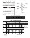
Circuiting selection should result in a circuit loading of 0.8
to 2.0 tons per circuit at design load. Circuit loading must be
evaluated at minimum load to ensure that it does not drop
below 0.6 tons per circuit. Solenoid valves may be used, if nec-
essary, to shut off the refrigerant supply to individual expansion
valves to maintain adequate coil circuit loading.
Compressor minimum unloading and TXV quantity is nec-
essary to determine minimum tonnage per circuit.
Minimum Unloading Equation:
Example:
Condensing Unit: 38ARS012
Minimum Unloading:33%
Coil: 6 row, 11 FPI, Half Circuit
Coil Tons/Circuit: 1.68
Total TXVs: 2
In the first example we will determine the tons/circuit when
both TXVs are active and the compressor is unloaded to its
minimum of 33%.
= .55 tons/circuit at minimum unloading UNACCEPTABLE
If we install a liquid line solenoid valve before one of the
TXVs and close it so that only one TXV is active when the
compressor is unloaded to its minimum of 33%, we see the
following:
= 1.10 tons/circuit at minimum unloading ACCEPTABLE
There are three different options to control tons/circuit when
using an unloading compressor. The first is to use drop sole-
noid valve control as illustrated above and let the suction cutoff
unloaders “ride” with the load. The second is to use drop
solenoid valve control as illustrated above with electric unload-
ers and let the control algorithm determine the combination of
solenoid valves and unloaders to limit tons/circuit to acceptable
limits. The third is to limit the minimum amount of unloading
so that tons/circuit is within acceptable limits.
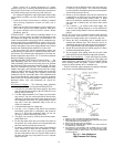
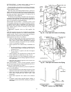
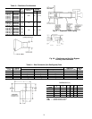
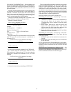
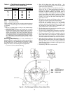
SPECIAL PIPING WITH 4 SPLITS PER COIL
Manifolding for 2-Face Splits
— Refer to Fig. 29 and exter-
nally manifold as follows:
1. Connect the 4 expansion valves to the 4 distributors on
each coil and connect the 4 suction lines to the
15-diameter-long risers as outlined in previous piping
instructions.
2. Install common liquid line for upper face split to first
(upper) and second expansion valves. Also, install a
common suction line from suction lines attached to first
(upper) and second suction header connections.
3. Repeat Step 2 for lower face split using third and fourth
distributor and suction connections.
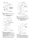
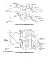
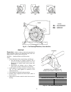
Manifolding for 2-Row Splits
— Refer to Fig. 30 and exter-
nally manifold as outlined for the 2-face splits with the
following exceptions:
1. Manifold in pairs, the first and third coil connections for
one split.
2. Manifold the second and fourth pairs of coil connections
for the other split.
NOTE: Split section using first and third pairs of coil connec-
tions should be first on, last off for coils with right hand (facing
direction of airflow) connections and the reverse for left hand
connections.
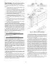
Hot Gas Bypass Connection with 4 Splits per Coil
— For
either face or row splits connect a hot gas bypass auxiliary side
connector to each distributor of coil split that is first on, last off.
Refer to installation instructions for Hot Gas Bypass.
(Tons/Circuit) x (Minimum Unloading)
x (Total # of TXVs)
# of TXVs Active
=
(1.68 Tons/Circuit) x (33% Minimum Unloading)
x (2 TXVs)
2 TXVs Active
=
(1.68) x (.33) x (2)
2
=
(1.68 Tons/Circuit) x (33% Minimum Unloading)
x (2 TXVs)
1 TXV Active
=
(1.68) x (.33) x (2)
1