


34
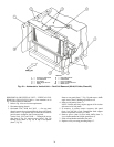
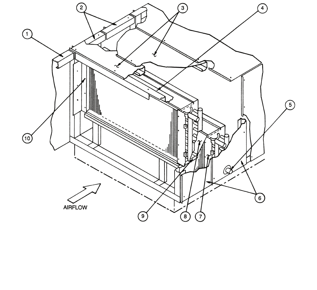
HORIZONTAL OR VERTICAL UNIT — VERTICAL COIL
REMOVAL (39LB,LC,LF,LH Units) — Item numbers are in
Fig. 41 unless otherwise indicated.
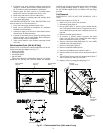
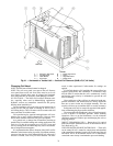
1. Refer to Fig. 4 for service area requirements.
2. Disconnect piping (Item 6).
3. Horizontal Unit, 39LB and 39LC — On top panel
(Item 4) remove screws located directly above side panels
(Items 2 and 7). Top panels may be removed from unit to
provide more workspace, but it is not required.
Vertical Unit, 39LF and 39LH — Through fan access
door (Item 2, Fig. 39), remove screws (Item 3, Fig. 39)
holding angle (Item 4, Fig. 39) to top of coil panels
(Item 7, Fig. 39).
Remove rear panel (Item 17, Fig. 39) and remove baffle
angle screws (Item 5) holding top baffle to coil.
4. Remove side panel(s) (Item 7).
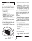
NOTE: Vertical units may require support of fan section
after removal of side panels.
5. If accessory is present, remove accessory side panel
(Item 1) on left side of unit. Detach filter track support
bracket if upstream accessory is a filter.
6. Remove screws (Item 8) from inside baffle (Item 3).
Leave baffle attached to left side panel (Item 2).
7. Slide coil and header end baffle from unit.
8. Replace coil by reversing preceding Steps 1-7.
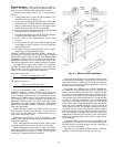
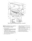
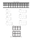
LEGEND
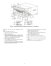
Fig. 40 — Horizontal or Vertical Unit — Dual Coil Removal (39LA,LD Units, Sizes 25)
1—Accessory Side Panel 6—Right Side Panels
2—Left Side Panel 7—Inside Baffle
3—Top Panels 8—Horizontal Baffle
4—Baffle Angle Screws 9—Upper Condensate Pan
5—Piping 10 — Baffle Screw