


38
10. Check fan shaft diameter at bearing mount. If worn by
more than .001 in. below nominal, shaft should be re-
placed.
11. Install new bearing, tighten holddown bolts and then
tighten bearing locking collar and setscrews.
12. Make certain fan wheel does not rub sides of fan housing
after installing new bearings.
13. Recoat fan shaft with a rust inhibitor or grease.
14. Replace sheave and belts. Adjust and align as described
in Installation sections on installing sheaves and V-belts.
15. Remove insulation protection.
16. Replace access panels.
17. Restore electrical power.
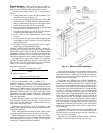
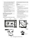
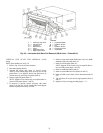
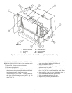
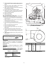
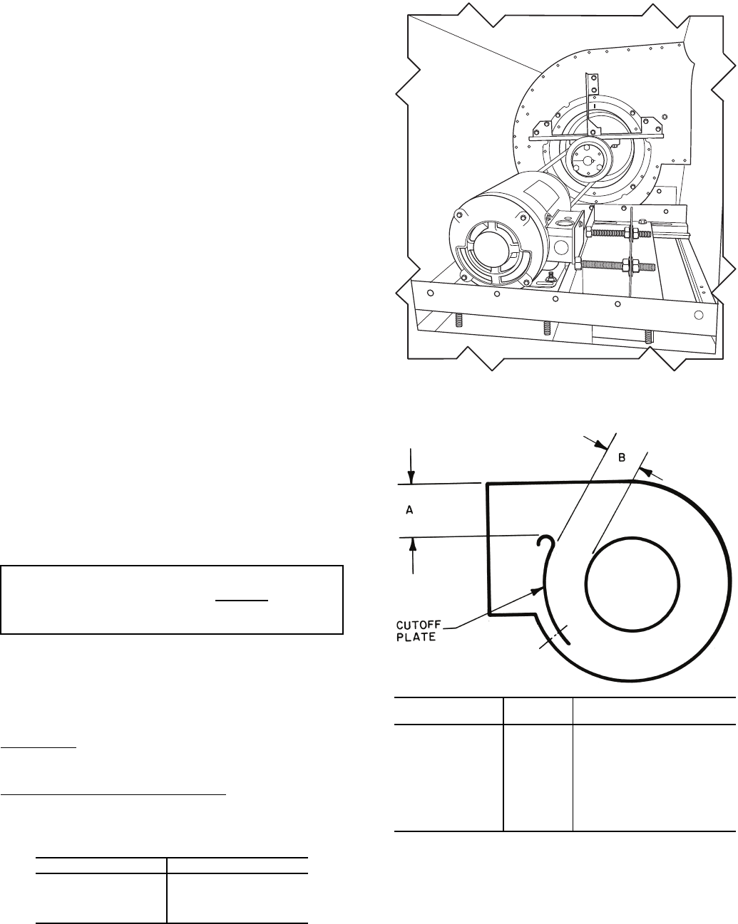
Fan and Shaft Removal (Fig. 44) — The fan wheel
and shaft may be removed through inlet side of fan housing.
1. Remove drive belts as described in Fan Shaft Bearing Re-
moval on page 36.
2. Block up fan wheel within housing to prevent dropping
when bearing bolts are removed.
3. Loosen and remove bearing holddown bolts.
4. Remove bearing support channels and inlet ring from one
side.
5. Remove fan shaft and fan wheel from unit.
6. Remove fan shaft from fan wheel.
7. Replace shaft and wheel into fan in the reverse order of
their removal.
8. Inspect bearings and if serviceable, replace on shaft.
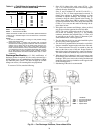
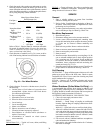
9. Align fan wheel and shaft assembly in fan scroll. Check
cutoff location if wheel failure damaged cutoff plate. See
Fig. 45.
10. Tighten bearing holddown bolts, bearing setscrews and
shaft setscrews.
11. Field balancing of shaft and wheel is recommended.
Lubrication
MOTORS — Lubricate in accordance with nameplate at-
tached to motor or with manufacturer’s recommendations
included with motor.
BEARINGS
Fan Bearings
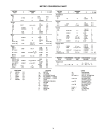
— Lubricate fan bearings every 3 months
with suitable bearing grease. Typical lubricants are given in
Table 13.
Inlet Vane and Outlet Damper Bearings
— These bearings
are oil-impregnated. Annually lubricate with a few drops of
nondetergent SAE (Society of Automotive Engineers) 20 oil.
Table 13 — Lubricant Data
*Preferred lubricant because it contains rust and oxi-
dation inhibitors.
IMPORTANT: Replacement shafts must have a diam-
eter tolerance at bearing mount of nominal.
Carrier-specified parts are recommended.
MANUFACTURER LUBRICANT
Sunoco Prestige 42
Texaco Multipak 2
Texaco Regal AFB-2*
Mobil Mobilplex EP No. 1
+ .0000
– .001
Fig. 44 — Fan Shaft and Bearing Removal
(Unit without IGVs shown)
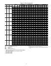
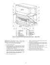
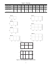
Fig. 45 — Fan Cutoff Plate Data (in.)
39L UNIT SIZE
CUTOFF
A
CUTOFF CLEARANCE
B
03 6
5
/
8
7
/
8
06 81
08 10
3
/
8
1
1
/
2
10 9
3
/
4
1
3
/
8
12 9
3
/
4
1
3
/
8
15 12 1
5
/
8
18 15
3
/
4
2
21 15
3
/
4
2
25 20
1
/
2
2
11
/
16