


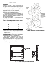
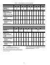
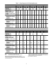
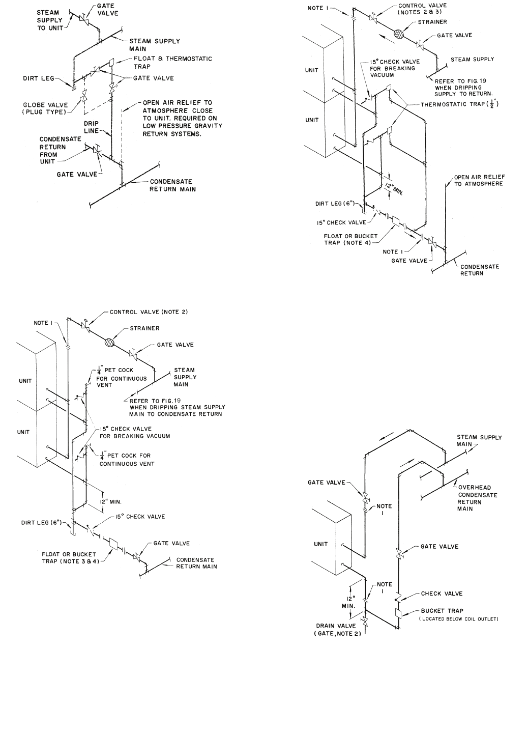
16
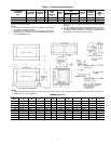
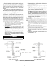
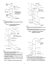
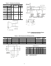
NOTES:
1. A bypass is necessary around trap and valves when continu-
ous operation is necessary.
2. Bypass to be the same size as trap orifice but never less than
1
/
2
inch.
Fig. 19 — Dripping Steam Supply to
Condensate Return
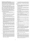
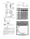
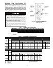
NOTES:
1. Flange or union is located to facilitate coil removal.
2. When a bypass with control is required.
3. Flash trap can be used if pressure differential between supply
and condensate return exceeds 5 psi.
4. Coils with different pressure drops require individual traps. This
is often caused by varying air velocities across the coil bank.
5. Dirt leg may be replaced with a strainer. If so, tee on drop can
be replaced by a reducing ell.
6. The petcock is not necessary with a bucket trap or any trap
which has provision for passing air. The great majority of high
pressure return mains terminate in hot wells or deaerators
which vent the air.
Fig. 20 — Multiple Coil High Pressure Piping
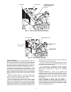
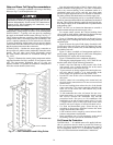
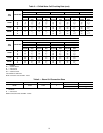
NOTES:
1. Flange or union is located to facilitate coil removal.
2. When control valve is omitted on multiple coils in parallel air
flow.
3. When a bypass with control is required.
4. Coils with different pressure drops require individual traps. This
is often caused by varying air velocities across the coil bank.
Fig. 21 — Multiple Coil Low Pressure
Piping Gravity Return
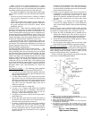
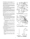
NOTES:
1. Flange or union is located to facilitate coil removal.
2. To prevent water hammer, drain coil before admitting steam.
3. Do not exceed one foot of lift between trap discharge and
return main for each pound of pressure differential.
4. Do not use this arrangement for units handling outside air.
Fig. 22 — Condensate Lift to Overhead Return