


25
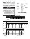
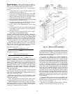
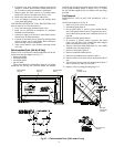
Electric Heaters — Electric heaters may be factory in-
stalled or drop shipped to the jobsite and field installed. The
heater can only be installed in the preheat-electric section.
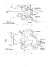
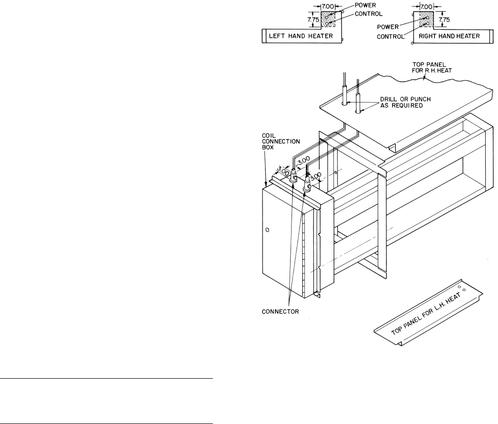
To install electric heater, refer to Fig. 31 and proceed as
follows:
1. Locate preheat-electric section already mounted on unit
and remove protective shipping cover.
2. Locate crate containing electric heater and verify heater
matches the unit. Unit hand and heater hands must agree.
3. Remove both knockout slugs (power and signal). Install
conduit connectors in top of coil connection box.
4. Remove top panel of the preheat-electric section and drill
or punch 2 holes are specified in Fig. 31.
5. Insert the electric heater into unit. It must slide between
2 angles located on the bottom of the section.
6. Secure heater to the preheat-electric section using
4 screws.
7. Locate top panel of section. Run conduit through top pan-
el and tighten conduit connectors. Lower top panel and
replace panel on unit.
8. Complete wiring per wiring diagram and job require-
ments. Follow all applicable local codes.
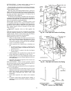
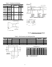
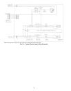
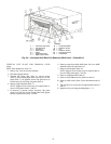
CONNECT POWER AND CONTROL WIRES — Heater wir-
ing schematic is located on control box panel. (Figure 32 shows
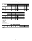
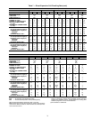
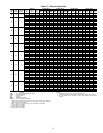
typical wiring details.) Electrical data for each standard heater
arrangement is shown in Table 10. Verify that minimum airflow
requirement (minimum coil face velocity, fpm) will be met,
especially on applications where variable air volume is supplied.
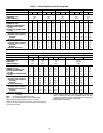
Use copper power supply wires rated for 75 C minimum.
On 250-v or greater applications, use 600-v rated wiring. Size
wires to carry 125% of current load on each set of terminals
(Table 11). Use the following formulas as required:
Single-phase line current
Three-phase line current
(kW per set of terminals) (1000) = (voltage) (1.73)
Note that if the heater is rated at 50 kW (or more) and is con-
trolled by a cycling device such as a multi-stage thermostat, or
a step controller, conductors may be sized at 100% of load
amperes (as in Tables 10 and 11) per National Electrical Code
(NEC) Section 424-22. Heater construction and application
information (Tables 10 and 11) are based upon Underwriters’
Laboratories (UL) Space Heating Standard No. 1096 and the
requirements of the NEC. Installer is responsible for observing
local code requirements.
Install a disconnect switch or main circuit breaker in accor-
dance with NEC and other applicable codes. Locate so that it is
easily accessible and within sight of heater control box (per
NEC Article 424-19 and 424-65).
Weatherproof junction boxes have no knockouts for wire
entrance. Drill or punch holes for conduit as required and make
all junctions watertight.
Where field-supplied thermostats are used, isolate circuits
to prevent possible interconnection of control circuit wiring.
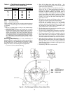
Where field-supplied step controller is used, connect steps
to terminals as marked on wiring schematic. When connecting
multi-stage heaters, wire stage no. 1 so that it is first stage on,
last stage off. Connect thermostats as required.
Provide sufficient clearance for convection cooling of heat-
ers with solid-state controllers. Provide at least 5-in. of free air
space above and below cooling fins extending from heater ter-
minal box. Be sure to connect interlock terminals F1 and F2 to
auxiliary contacts on fan starter.
Each heater has 2 different types of factory-installed ther-
mal cutouts for overtemperature protection; an automatic reset
thermal cutout for primary protection and a manual reset ther-
mal cutout to protect against failure of the primary system.
Also provided is an airflow pressure differential switch to pre-
vent the heater from operating when the fan is not in operation
or airflow is restricted or insufficient. The primary automatic
reset cutout is a bi-metal disk-type cutout. It is wired into the
control circuit which operates the magnetic disconnecting con-
tactors (the same contactors which also switch on and off the
various steps of the coil). The secondary manual reset cutout is
a bi-metal disk-type cut-out. This secondary thermal cutout is
load carrying and is installed in each heater subcircuit. The pri-
mary and secondary overtemperature protection systems are
independent of each other. The secondary system is designed to
protect against possible failure of the primary system to deen-
ergize the heater.
Subcircuits in the heaters are designed in compliance with
paragraph 424-22 of the NEC. The coil is subdivided into cir-
cuits that draw no more than 48 amps each and is fused for at
least 125% of the circuit rating.
Pitot tube is to be positioned so that the airflow switch is ac-
tuated by a minimum negative pressure of 0.07 in. wg.
=
1 (kW per set of terminals) (1000)
voltage
=
(kW per set of terminals) (1000)
(voltage) (1.73)
Fig. 31 — Electric Heater Installation