


11
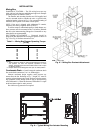
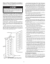
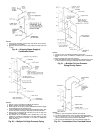
Install Fan Motor — For field installation of motors, be
sure electrical junction box is toward the center of the unit.
This is necessary for drive and belts to be properly tightened.
Use smallest slots in motor mounting base that will accommo-
date motor and allow minimum overhang (Fig. 13). Be sure
that motor holddown bolts are tight on field-installed motor.
JUNCTION BOX CONDENSATE PREVENTION — When
air handlers are installed outdoors in a high humidity environ-
ment or indoors where the apparatus room is used as a fresh air
plenum, precautions must be taken to prevent condensation
from forming inside the junction box of the internally mounted
motor.
Standard installation practice is to mount the motor starter
or fused disconnect box adjacent to the air handler and enclose
the power wiring to the motor in flexible conduit.
The sheet metal housing of the disconnect switch or motor
starter is not airtight (even when a box meeting NEMA
[National Electrical Manufacturers Association] IV standards
is used). Thus, warm moist air can migrate through the flexible
conduit to the junction box on the motor. With the motor
located inside the unit, the motor temperature is that of the cool
supply air; thus, condensate can form inside the junction box
and, possibly, on the live terminal lugs.
To prevent the moist air from migrating through the conduit
to the motor, seal the power wires inside the flexible conduit at
the motor starter or fused disconnect.
Use a nonconductive, nonhardening sealant. Permagum
(manufactured by Schnee Morehead) or sealing compound,
thumb grade (manufactured by Calgon), are acceptable
materials.
POWER KNOCKOUTS — Panels are not provided with
knockouts for the fan motor power wiring. Openings must be
drilled or punched in the exterior panels of the unit. It is recom-
mended that power wiring be routed through the discharge
panel whenever possible, as this panel is rarely removed for
service access.
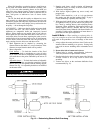
Install Sheaves on Motor and Fan Shafts —
Factory-supplied drives are prealigned and tensioned, however,
Carrier recommends that you check the belt tension and align-
ment before starting the unit. Always check the drive align-
ment after adjusting belt tension.
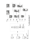
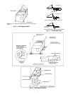
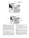
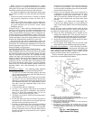
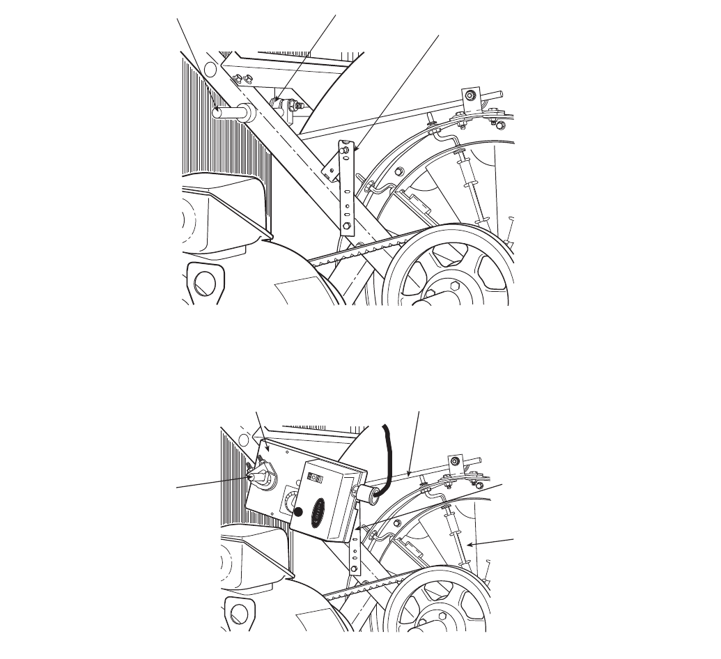
JACKSHAFT CRANKARM
ANTIROTATION STRAP
INSTALLED (ACTUATOR
NOT SHOWN FOR
CLARITY)
IGV ACTUATOR
CONNECTING ROD
ANTIROTATION
STRAP
INLET GUIDE
VANES (IGV)
IGV
JACKSHAFT
Fig. 11 — IGV Actuator Bracket Installation
Fig. 12 — IGV Actuator Mounting