


28
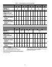
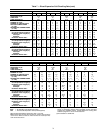
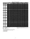
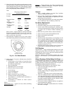
Table 11 — Field Wiring for Incoming Conductors
Sized for 125% of Heater Load
LEGEND
*Values are based on Table 310-16 of the NEC (National Electrical
Code) for 75 C insulated copper wire. Not more than 3 conductors
in a raceway.
NOTES:
1. Be sure to consider length of wiring run and possible voltage
drops when sizing wires.
2. Field power wiring — Heaters are furnished with a terminal
block sized for incoming copper conductors with 75 C insulation
rated to carry at least 125% of the heater load. However, con-
ductors can be sized to carry 100% of the heater load if the
heater is rated at 50 kW or more, and the heater is controlled by
a cycling device such as a multi-stage thermostat, step control-
ler, or SCR (silicon control rectifier) power controller. Terminal
blocks and knockouts are sized to handle either 100% or 125%
conductors.
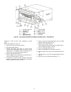
Discharge Modification — If field modification of
discharge position is required, 39L fans can be converted (by a
skilled mechanic) to any standard hand and discharge without
any additional parts. (NOTE: This does not apply to a model
change conversion.) All mounting holes are prepunched.
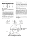
To convert a 39L fan, note the following:
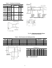
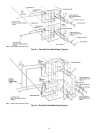
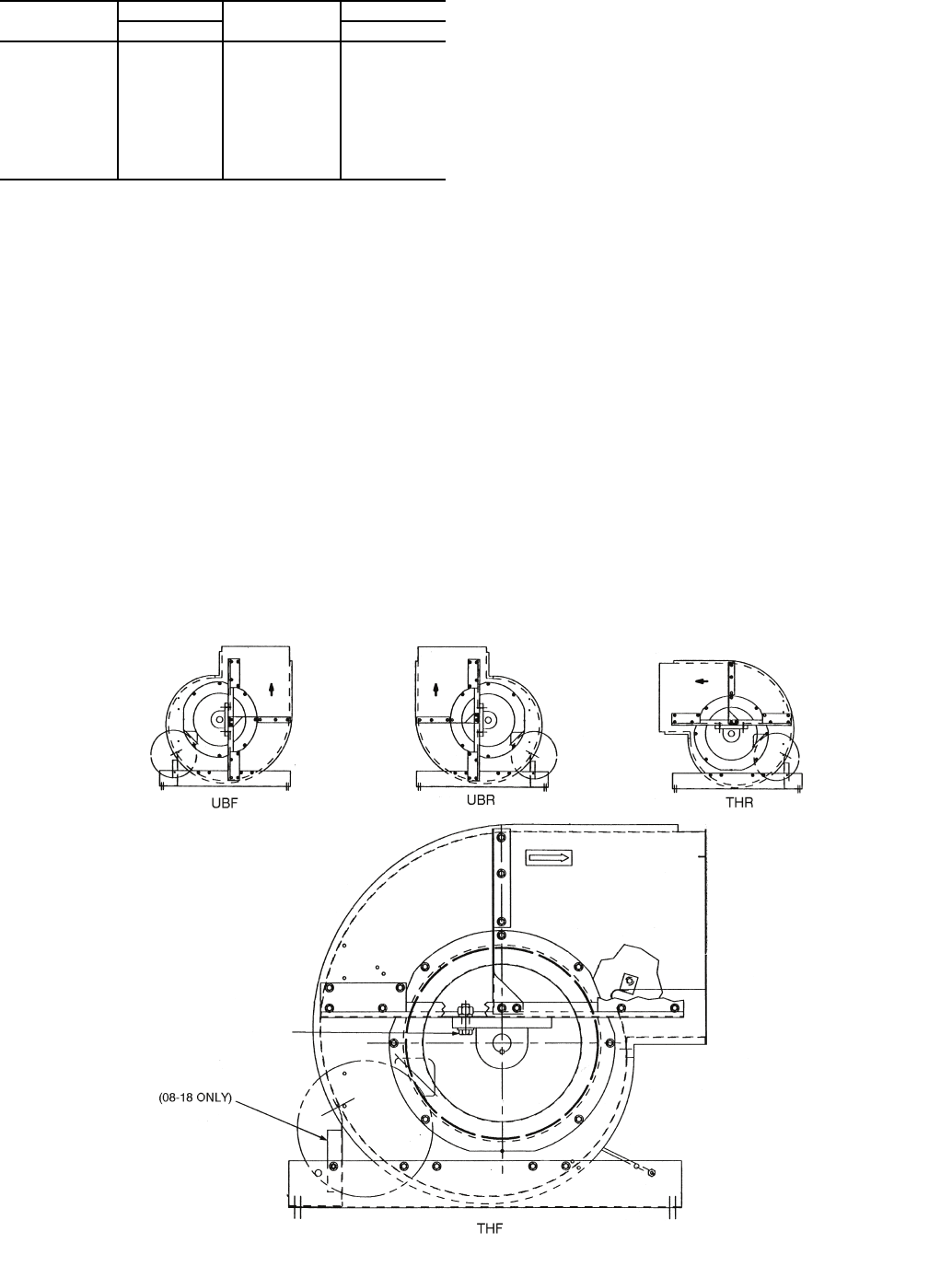
1. Sizes 03-18 without inlet guide vanes (IGVs) — See
Fig. 33. It is not necessary to remove the bearing support
channels from the fan housing.
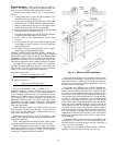
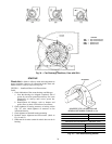
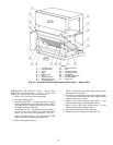
Sizes 21 and 25 without IGV and 06-25 with IGVs —
See Fig. 34. The “A” frame support must be removed. To
change from upblast to horizontal discharge or from
horizontal to upblast discharge, the bearings must be
relocated to keep the wheel centered in the housing. To
change from upblast front (UBF) to upblast rear (UBR)
or from top horizontal front (THF) to top horizontal rear
(THR) or vice versa, turn the entire fan housing 180 de-
grees about its base.
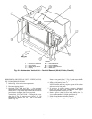
2. Inlet guide vane actuators and linkages, where provided,
may be moved to the opposite fan scroll side sheet.
NOTE: The swivel joint must be at the 12 o’clock posi-
tion on the IGV assembly. (See Fig. 12.) The jackshaft
crankarm, attached to the jackshaft at the “A” frame, will
sit vertically up on all units. Figure 12 illustrates a jack-
shaft crankarm in the vertical up position.
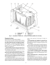
3. The fan shaft may be driven out and reinstalled to place
the drive pulley on the opposite end.
4. The fan scroll is prepunched for horizontal or vertical dis-
charge to match the support angles at the base of the unit.
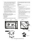
5. The motor and motor base may be rotated to place the
motor at the front or rear of the unit. Proper location is
that which results in the longest drive center line distance.
The motor conduit box location may need to be reversed.
6. When hand of fan is changed, it may be necessary to turn
the discharge panel inside-out to fit correctly with the fan
discharge. In this case, remove the existing insulation and
install new duct-liner type insulation on the opposite side
of the discharge panel.
7. Rebalancing of the unit is recommended.
WIRE SIZE
(AWG or kcmil)
LOAD AMPS*
WIRE SIZE
(AWG or kcmil)
LOAD AMPS*
Copper Copper
12 16 1/0 120
10 24 2/0 140
8 40 3/0 160
6 52 4/0 184
4 68 250 204
3 80 300 228
2 92 350 248
1 104 400 268
500 304
AWG — American Wire Gage
kcmil — Thousand Circular Mils
Fig. 33 — Fan Discharge Positions, Fans without IGVs
LEGEND
THF — Top Horizontal Front
THR — Top Horizontal Rear
UBF — Upblast Front
UBR — Upblast Rear