


35
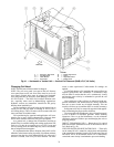
Changing Coil Hand
NOTE: Electric heat coil hand cannot be changed.
NOTE: The coil cover panel is not part of the coil. Remove
cover panel from end of unit. New holes must be cut in coil
cover panel. Original holes must be plugged and insulated.
New side panels may be necessary when changing coil hand.
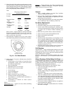
NU-FIN COILS — The NuFin coil is airflow direction sensi-
tive, especially when used in dehumidifying applications.
Hydronic versions are counterflow circuited for full gravity
draining when installed level.
Correct installation will result in the typical bottom inlet on
leaving air face and top outlet on entering air face of coil, a
self-venting design. This will ensure cold air contact with cold
water, and warm air with hot water.
Coil repositioning for opposite hand application will com-
promise one or more of these characteristics. However, there
will be those situations where this may prove acceptable.
As a general rule, a change from counterflow circuiting to
parallel flow for sensible heating and cooling applications will
result in a 5% drop in net capacity per row of coil. In one and
two row heating coils, the actual drop may not be measurable,
thus of insignificant consequence.
It is important that the airflow direction of the NuFin coil be
adhered to when latent cooling is possible. Significant moisture
carryover from the face of the dehumidifying coil will result if
this rule is violated, even at very low face velocities. The same
result is often experienced if after-market fin coatings are
applied.
If a NuFin hydronic coil is installed with correct airflow, but
opposite piping hand, and counterflow is maintained, steps
must be taken to ensure that the coil is continuously vented,
and that the water velocity is maintained to prevent the coil
from air-binding.
Hot or cold areas of the coil face (or otherwise broad tem-
perature differences and stratification) are usually indications
that one or more circuits are air-locked internally. This can
result in coil freeze-up (a condition NOT covered by warranty).
Refrigerant coils may be rotated for opposite hand applica-
tions, maintaining the proper airflow direction.
Do not reposition the distributor(s), they will perform equal-
ly well in upflow or downflow positions. When soldering
expansion valves to up-feed distributors, use the minimum
satisfactory amount of solder to prevent damaging the valve or
plugging passages.
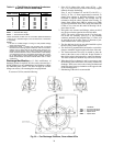
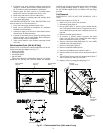
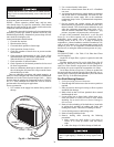
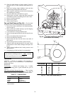
DIRECT EXPANSION COILS — Rotate the coil in vertical
plane and reinstall. Distributor must be on downstream side of
coil. (Refer to Fig. 42).
CHILLED WATER AND HOT WATER COILS — These coils
can be rotated. If coil is rotated in vertical plane and reinstalled
with counterflow maintained, supply will be at the top of the coil
and return will be at the bottom. Ensure coil is continuously
vented and water velocity is maintained to prevent air binding.
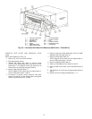
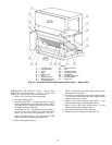
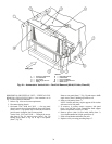
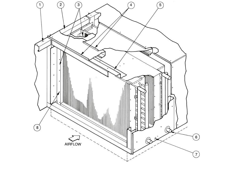
LEGEND
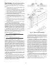
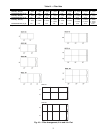
Fig. 41 — Horizontal or Vertical Unit — Vertical Coil Removal (39LB,LC,LF,LH Units)
1—Accessory Side Panel 5—Baffle Angle Screw
2—Left Side Panel 6—Piping
3—Inside Baffles 7—Right Side Panel
4—Top Panels 8—Baffle Screw