


19
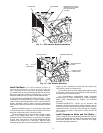
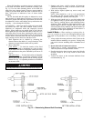
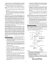
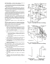
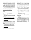
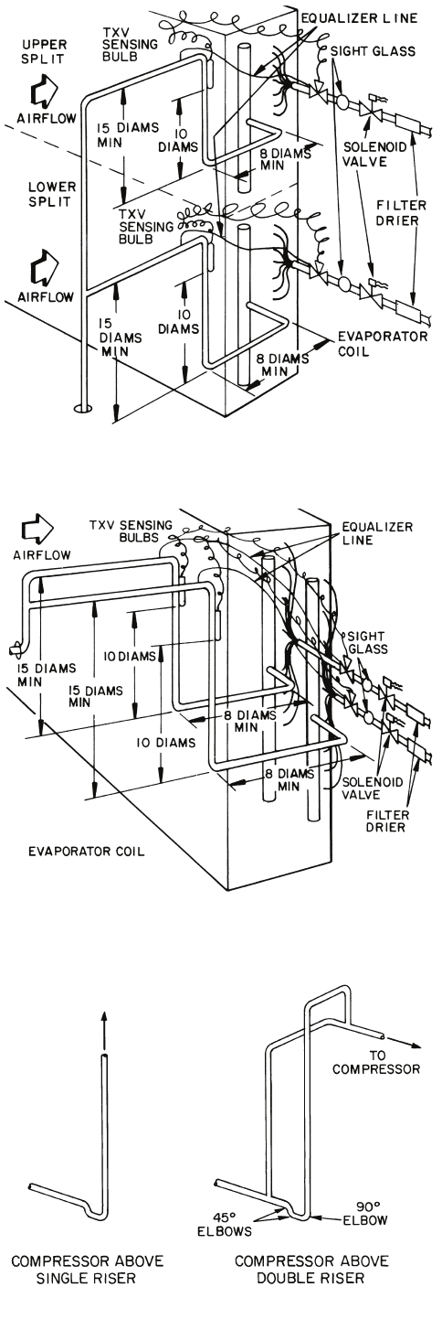
SUCTION PIPING — Connect suction piping as shown in
Fig. 24 for face split coil or Fig. 25 for row split coil.
Suction line from coil connection to end of the 15-diameter-
long riser should be same tube size as coil connection to ensure
proper refrigerant velocity.
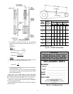
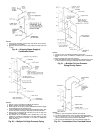
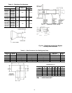
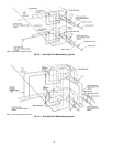
Refer to Carrier System Design Manual, Part 3, and size re-
maining suction line to compressor for a pressure drop equiva-
lent to 2.0 F. This will provide a total suction line header pres-
sure drop equivalent to approximately 2.5 F. Refer to Fig. 26
for piping risers to the compressor.
To minimize the possibility of flooded starts and compres-
sor damage during prolonged light load operation, install an ac-
cumulator in the suction line or a solenoid in the liquid line of
last-on, first off split in row-split applications.
EXPANSION VALVE PIPING — Distributor nozzles sized
for acceptable performance for a range of conditions are facto-
ry supplied. Use the AHU (Air-Handling Unit) selection pro-
gram in the Carrier electronic catalog to select optimal nozzle
sizes. Replace factory nozzle as necessary for best perfor-
mance. See Fig. 27.
Thermostatic expansion valves are field supplied. See
Fig. 27.
NOTE: Be sure that correct nozzle is installed in each distribu-
tor before installing expansion valve. Before installing field-
supplied nozzles, remove nozzle retainer rings and factory-
installed minimum-sized nozzles from distributors.
Install expansion valve (Fig. 27) as follows:
1. Wrap wet cloths around valve body to prevent excessive
heat from reaching diaphragm and internal parts. Do not
allow water to enter system. Disassemble expansion
valve before soldering, if accessible, for easy reassembly.
Use 95-5 tin-antimony soft solder.
2. Solder expansion valve outlet directly to distributor un-
less:
a. An adapter bushing or coupling is supplied by the
factory (solder adapter to distributor first, then to
expansion valve).
b. Hot gas bypass is required. (See Hot Gas Bypass
section, below.)
3. Solder expansion valve equalizer line to suction line and
locate control bulb on suction line as in Fig. 24 or 25.
4. Insulate expansion valve body, diaphragm assembly and
control bulb area to prevent charge migration and exces-
sive condensation.
5. Install filter drier ahead of expansion valve to ensure sat-
isfactory valve operation.
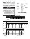
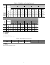
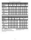
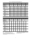
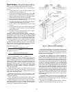
HOT GAS BYPASS — When low-load operation requires
use of hot gas bypass, hot gas must be introduced between ex-
pansion valve and distributor. See Table 9.
Install hot gas bypass connector (Fig. 28) in coil split that is
first on, last off as follows:
1. Remove distributor nozzle and retainer ring (area A) from
distributor and reinstall in inlet (area B) of side connector.
2. Solder side connector outlet to distributor inlet, using
silver solder or equivalent with 1300 to 1500 F melt
temperature.
3. Silver-solder expansion valve outlet to side connector
inlet.
4. If required, install factory-supplied adapter bushing or
coupling to connector inlet before soldering to expansion
valve outlet.
TXV — Thermostatic Expansion Valve
Fig. 24 — Face Split Coil Suction Line Piping
TXV — Thermostatic Expansion Valve
Fig. 25 — Row Split Coil Suction Line Piping
Fig. 26 — Suction Line Riser Piping