


30
6. Check fan speed with a strobe-type tachometer or use the
following formula: Obtain the motor rpm from the fan
motor nameplate and read sheave pitch diameters marked
on the fan and motor pulleys, or estimate the pitch diame-
ters by using the pulley outside diameters.
Then:
Example:
Actual
Approximate
Nameplate Motor
Rpm = 1760 1760
Mtr Sheave Pitch
Diameter = 8.9 in. 9.0 (OD)
Fan Sheave Pitch
Diameter = 12.4 in. 12.5 (OD)
Fan Rpm = 1760 x 8.9
1760 x 9
= 12.4 12.5
= 1263 Rpm 1267 Rpm
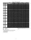
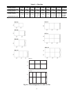
Refer to Table 1, Physical Data for maximum allowable
fan speeds for standard wheels. Excessive fan speed may
result in condensate carryover from cooling coil or fan
motor overload and wheel failure.
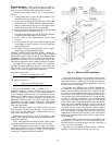
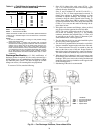
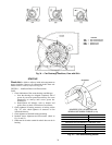
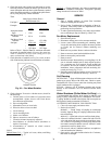
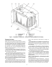
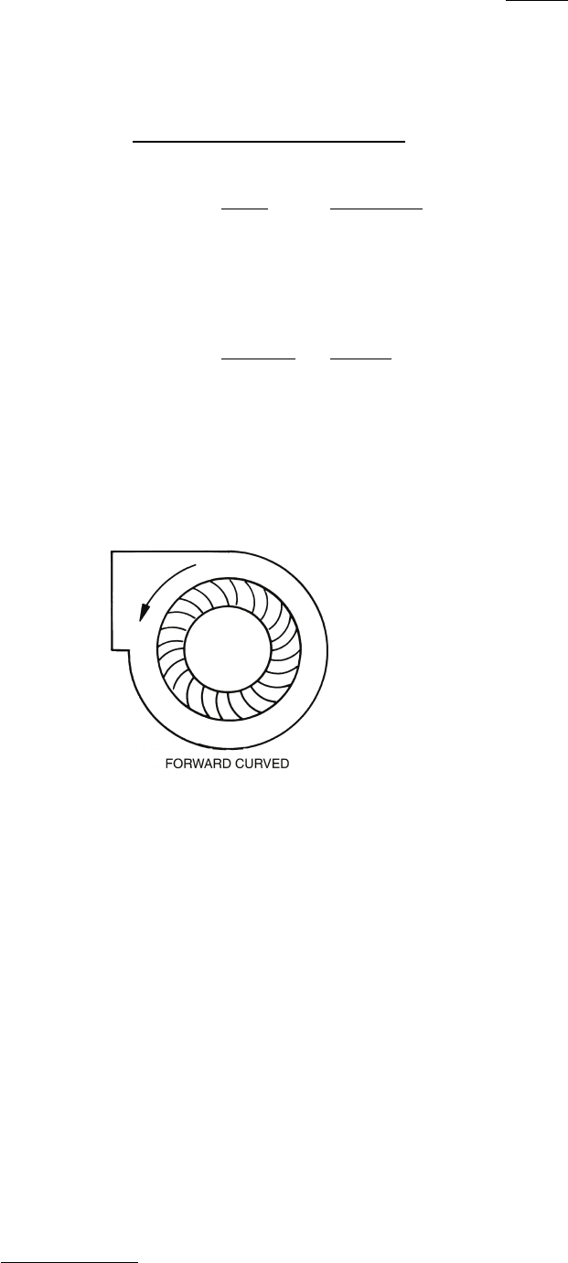
7. Check direction of rotation (see Fig. 36). Arrow on drive
side of fan housing indicates correct direction of rotation.
8. Check vibration. If excessive vibration occurs, check for
the following:
a. Variable sheave (if air balance of system has been
accomplished: replace sheave with fixed sheave
for continuous application).
b. Drive misalignment.
c. Mismatched, worn or loose belts.
d. Wheel or sheaves loose on shaft.
e. Loose bearings.
f. Loose mounting bolts.
g. Motor out of balance.
h. Sheaves eccentric or out of balance.
i. Vibration isolators improperly adjusted.
j. Out-of-balance or corroded wheel (rebalance or
replace if necessary).
k. Accumulation of material on wheel (remove
excess material).
COILS
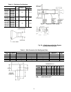
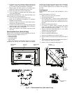
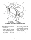
Chilled Water Coil
— Typical coil vents, drains, and lifting
points are shown in Fig. 17.
DX Coil
— Charge refrigerant. Also refer to condensing unit
service and installation instructions. Refrigerant operating
charge for unit coil is shown in Table 1.
SERVICE
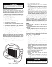
General
1. Place a suitable walkway to protect floor insulation
whenever entering the fan section.
2. Review Safety Considerations at beginning of these in-
structions. Good safety habits are important tools when
performing service procedures.
3. To make speed measurements, use a strobe-style tachom-
eter or calculate per Step 6 of Start-Up, Check List.
Fan Motor Replacement
1. Shut off motor power.
2. Disconnect and tag power wires at motor terminals.
3. Loosen motor brace-to-mounting-rail attaching bolts.
Loosen belt tensioning bolts to adjust the motor position
so V-belts can be removed without stretching over
grooves.
4. Mark belt as to position. Remove and set aside belts.
5. Remove motor to motor bracket holddown bolts.
6. Remove motor pulley and set aside.
7. Remove motor.
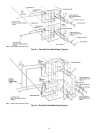
8. Install new motor. Reassemble by reversing Steps 1-6. Be
sure to reinstall multiple belts in their original position.
Use a complete new set if required. Do not stretch belts
over sheaves. Review the sections on motor and sheave
installation, sheave alignment and belt tensioning dis-
cussed previously (Fig. 13-15).
9. Reconnect motor leads and restore power. Check fan for
proper rotation as described in Start-Up, Check List.
Coil Cleaning
DETERGENT — Spray mild detergent solution on coils with
garden-type sprayer. Rinse with fresh water. Check to ensure
condensate line is free. Excess water from cleaning may flood
unit if condensate line is plugged.
STEAM — Remove coil to facilitate cleaning and prevent
damage to unit insulation. See Coil Removal section which
follows.
Winter Shutdown (Chilled Water Coil Only) — It
is recommended that auxiliary drain piping be added to coil
piping if yearly winterizing of coils is anticipated. This auxilia-
ry piping should be located at the highest and lowest point on
the respective header connection for each coil.
ANTIFREEZE METHODS OF COIL PROTECTION
1. Close coil water supply and return valves.
2. Drain coil as follows:
Method I — ‘Break’ flange of coupling at each header
location. Separate flange or coupling connection to facili-
tate coil draining.
Method II — Open both valves to auxiliary drain piping.
3. After coil is drained, Method I, connect line with a service
valve and union from upper nozzle to an antifreeze reser-
voir. Connect a self-priming reversible pump between the
low header connection and the reservoir. Method II, make
connection to auxiliary drain valves.
4. Fill reservoir with any inhibited antifreeze acceptable to
code and underwriter authority.
5. Open service valve and circulate solution for 15 minutes;
then check its strength.
Fan Rpm =
Motor Rpm x Motor Sheave
Pitch Diameter (in.)
Fan Sheave Pitch Diameter (in.)
Fig. 36 — Fan Wheel Rotation