


Carrier
Page 15.2
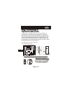
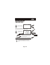
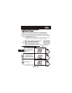
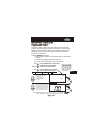
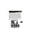
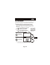
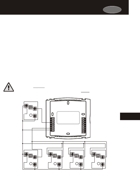
Installing the Remote SensorsInstalling the Remote Sensors
Up to eight wired or wireless remote sensors may be installed on the
thermostat (RS1) to control the temperature in other rooms. If more
than one sensor is connected to (RS1) the thermostat will average the
sensors to determine the displayed temperature reading. One wired or
wireless remote sensor may be installed to read the outside temp-
erature (RS2). If a sensor(s) is connected to RS1 and is programmed
to control the thermostat, the degree icon on the thermostat will blink
once per second to indicate that a remote sensor reading is being dis-
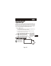
played. The wired sensor can be connected to the thermostat with up
to 150’ of 18 ga., 300’ of 20 ga., or 450’ of 22 ga. unshielded, therm-
ostat wire. If multiple sensors are wired to the thermostat, then the
total wiring distance of the furthest sensor should be used in determin-
ing the appropriate wire gauge. The wired sensor can be connected to
the thermostat using a two or three wire installation. If a two wire instal-
lation is required, then RS+5 must be connected to RSGND (see below).
This wire MUST be completely separated from the thermostat
or any other control wiring and must NOT be in the same
conduit as high voltage wiring.
15
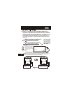
See the Remote Sensor accessory for further details.
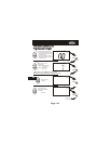
RS1-1
Y1
G
R
C
MISC2
CK1
CKGND
W1/O/B
MISC1
RS+5
RS1
RSGND
W2
RS2
MISC3
RS1-4RS1-3RS1-2
RS2
RS
RS-GND
RS+5
RS
RS-GND
RS+5
RS
RS-GND
RS+5
RS
RS-GND
RS+5
RS
RS-GND
RS+5