


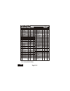
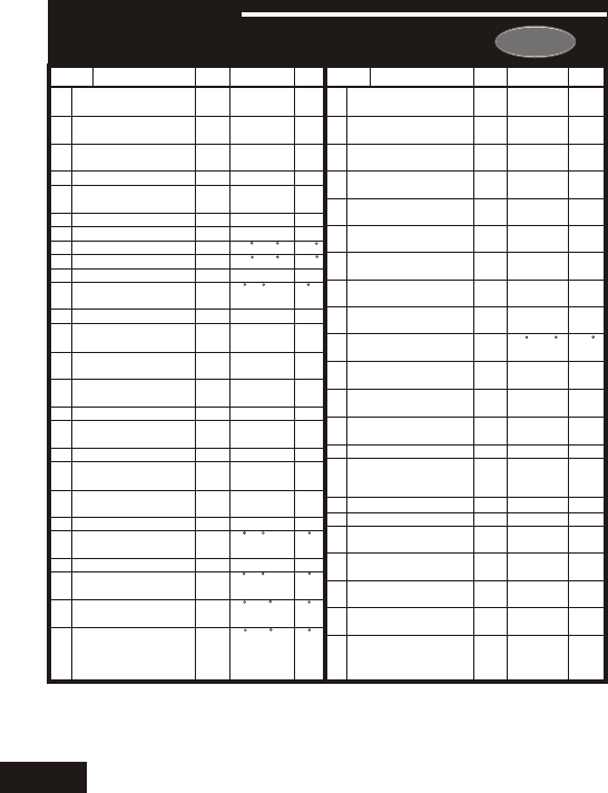
24
Description
Df*
Step#
Range
Step#
Description
Range
Df*
2
2
Off
Off
NO
7
Mo
7am
9pm
80
No
Off
Yes
NO
Occ.
1
No
Off
- -
0
0
0
- -
1
2
3
4
5
6
7
8
9
10
11
12
13
14
15
16
17
18
19
20
21
22
23
24
25
26
Programmable
Thermostat
Auto-Changeover
Thermostat
Fan Off Delay
Fan Purge
Thermoglow
Backlight
F or C
Security Level
Max Heat Setpoint
Min Cool Setpoint
Cool to Dehumidify
Maximum Dehum
Overshoot
Reheat Operation
DEHUM Terminal
Polarity
Energy Watch -
Heat Timer
Energy Watch -
Cool Timer
Override Run-Time
Reset Service
Humidify Icon
Reset UV Light Icon
Heatpump Jumper
Setting
Reversing Valve
Jumper Setting
Electric Heat
Minimum Heat/Cool
Differential
Cycles Per Hour
Deadband/Temp.
Swing 1st Stage
Deadband/Temp.
Swing 2nd Stage
Deadband/Temp.
Swing 3rd Stage
Yes
Yes
0
0
Au-
to
F
0
80
65
Off
3
Off
NC
- -
- -
- -
- -
- -
- -
- -
- -
2
6
2
2
2
Yes/No
Yes/No
0, 30, 60,
90
0 - 3 hrs.
Auto/On/
Off
F/C
0 - 3
35 - 99
35 - 99
On/Off
0 - 5
On/Off
NO/NC
read only
read only
read only
read only
read only
read only
read only
read only
0 - 6
d1, d, 2-6
1 - 6
0 - 10
0 - 10
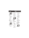
Pg#
4.2
4.3
7.3
7.4
8.2
8.2
8.4
8.4
8.4
10.4
10.4
10.5
10.6
11.2
11.3
11.4
11.5
11.6
12.2
12.2
12.3
13.2
13.3
13.5
13.5
13.5
0-60min
0-60min
On/Off
Off/Time/
Temp/Aux
NO/NC
7Day/
1Day
Mo - Su
24 Hour
24 Hour
35 -125
Yes/No
On/Off
Yes/No
NO/NC
Occ. 1/
Service
Pan
Yes/No
Off/On
read only
0 - 1950
0 - 1990
0 - 1990
- -
27
28
29
30
31
32
33
34
35
36
37
38
39
40
41
42
43
44
45
46
47
48
Minutes Between
Stage 1 & 2
Minutes Between
Stage 2 & 3
2nd Stage turn off at
setpoint
Programmable
Output
Programmable
Output Polarity
7 Day/1 Day
Programmable Output
Programmable Output
Output Day of the Week
Programmable Output
Start Time
Programmable Output
Stop Time
Programmable Output
Temp. Setpoint
Thermostat control
to RS1?
Thermostat Sensor
Averaging
Dry Contact
Operation
Dry Contact Polarity
Dry Contact
Programming
Light Activated
Energy Save
Reset Service Filter
Icon
Service Filter Run
Time Set
UV Light Run-Time
Set
Service Humidify
Run-Time Set
Viewing the Remote
Sensor
Temperature(s)
Pg#
13.6
13.6
13.7
14.3
14.4
14.4
14.4
14.4
14.5
14.6
15.3
15.4
16.2
16.2
16.3
17.2
18.1
19.2
19.2
19.3
19.4
22.4
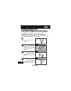
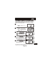
Page 24.1
SECTION 24
Advanced Setup TableAdvanced Setup Table
*Df = Factory Default Setting
Carrier