


Carrier
ECON
Page 10.2
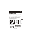
Setting a Thermostat Jumper for
Dehumidification Operation
Setting a Thermostat Jumper for
Dehumidification Operation
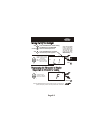
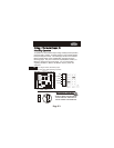
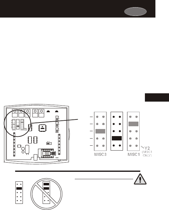
NEVER PUT MORE THAN ONE JUMPER
ON THE SAME MISC JUMPER BLOCK!
THIS MAY DAMAGE THE THERMOSTAT
MISC3
MISC3
OK
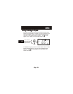
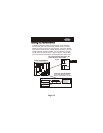
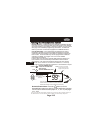
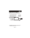
To control a MISC output for dehumidification, install the Humidity
Module and place the Humidity Jumper on HUM (see page 9.2).
Then place the MISC1, MISC2, or MISC3 jumper on the terminal
labeled DEHUM (see diagram below). This will supply 24VAC to the
selected MISC terminal based on the programming in the following
pages. Only one of the three outputs (MISC1, MISC2, or MISC3) is
required to have a jumper. For more information regarding the
MISC1, MISC2, and MISC3 outputs, please see section 21.
10
W3
PROG
HUM
DEHUM
MISC3 MISC2 MISC1
Y2
(MISC1
ONLY)
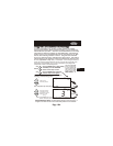
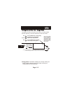
In the diagram below, the MISC2 jumper has
been set for DEHUM (dehumidification) operation.
IMPORTANT CAUTION
HP
GAS
B
O
ELEC
GAS
(FAN)
W1
Y1
G
R
C
MISC2
W2
MISC1
Rs2
RSGND
MISC3
RS+5
Rs1
W3
HUM
DEHUM
MISC3 MISC2 MISC1
Y2
(MISC1
ONLY)
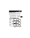
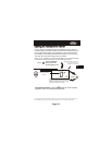
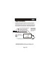
INSTALL HUMIDITY
MODULE WITH SENSING
ELEMENT OUTWARD
HUM
NO HUM
1
2
4
6
8
X
Z
1
5
7
9
Y
3
PROG
CK1
CKGND
ECON