


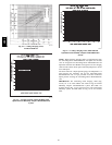

52
Step 11 —Combustion--Air Blower
Clean periodically to ensure proper airflow and heating
efficiency . Inspect blower wheel every fall and periodically
during heating season. For the first heating season, inspect blower
wheel bimonthly to determine proper cleaning frequency.
To inspect blower wheel, remove draft hood and screen. Shine a
flashlight into opening to inspect wheel. If cleaning is required,
remove motor and wheel as follows:
1. Slide burner access panel out.
2. Remove the 5 screws that attach induced-draft motor
assembly to the vestibule cover.
3. Slide the motor and blower wheel assembly out of the
blower housing. The blower wheel can be cleaned at this
point. If additional cleaning is required, continue with
Steps 4 and 5.
4. To remove blower from the motor shaft, remove
2setscrews.
5. To remove motor, remove the 4 screws that hold the
motor to mounting plate. Remove the motor cooling fan
by removing one setscrew. Then remove nuts that hold
motor to mounting plate.
6. To reinstall, reverse the procedure outlined above.
Step 12 —Limit Switch
Remove blower access panel (Fig. 8). Limit switch i s located on
the fan deck.
Step 13 —Burner Ignition
Unit is equipped with a direct spark ignition 100% lockout
system. Integrated Gas Unit Controller (IGC) is located in the
control box (Fig. 13). A single LED on the IGC provides a visual
display of operational or sequential problems when the power
supply is uninterrupted. The LED can be observed through the
viewport. When a break in power occurs, the IGC will be reset
(resulting in a loss of fault history) and the evaporator fan on/off
times delay will be reset. During servicing, refer to the label on
the control box cover or Table 39 for an explanation of LED error
code descriptions.
If lockout occurs, unit may be reset by interrupting power supply
to unit for at least 5 seconds.
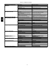
Table 38—LED Error Code Description*
LED INDICATION ERROR CODE DESCRIPTION
ON
Normal Operation
OFF
Hardware Failure
1Flash†
Evaporator Fan On/Off Delay Modified
2Flashes
LimitSwitch Fault
3Flashes
Flame Sense Fault
4Flashes
4 Consecutive Limit Switch Faults
5Flashes
Ignition Lockout Fault
6Flashes
Induced-Draft Motor Fault
7Flashes
Rollout Switch Fault
8Flashes
Internal Control Fault
9Flashes
SoftwareL ockout
LEGEND
LED — Light-Emitting Diode
*A 3-second pause exists between LED error code flashes. If more than
one error code exists, all applicable codes will be displayed in numeri-
calsequence.
†Indicatesa code thatisnot an error. Theunit will continue to operate
when this code isdisplayed.
IMPORTANT: Refer to Troubleshooting Tables for additional
information.
Step 14 —Main Burners
At the beginning of each heating season, inspect for deterioration
or blockage due to corrosion or other causes. Observe the main
burner flames and adjust, if necessary.
FURNACE DAMAGE HAZARD
Failure to follow this caution may result in reduced furnace
life.
When servicing gas train, do not hit or plug orifice spuds.
CAUTION
!
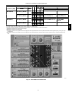
Removal and Replacement of Gas Train
(See Fig. 63 and
64)
1. Shut off manual gas valve.
2. Shut off power to unit, tag disconnect.
3. Remove compressor access panel.
4. Slide out burner compartment side panel.
5. Disconnect gas piping at unit gas valve.
6. Remove wires connected to gas valve. Mark each wire.
7. Remove induced-draft motor , igniter, and s ensor wires at
the Integrated Gas Unit Controller (IGC).
8. Remove the 2 screws that attach the burner rack to the
vestibule plate.
9. Remove the gas valve bracket.
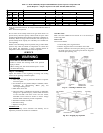
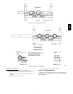
10. Slide the burner tray out of the unit (Fig. 64).
11. To reinstall, reverse the procedure outlined above.
12. Reinstall burners on rack.
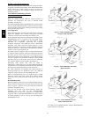
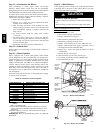
INDUCED-
DRAFT
MOTOR
MOUNTING
PLATE
INDUCED-
DRAFT
MOTOR
MANIFOLD
PRESSURE
TAP
VESTIBULE
PLATE
FLUE
EXHAUST
ROLLOUT
SWITCH
BLOWER
HOUSING
GAS
VALVE
BURNER
SECTION
C06152
Fig. 63 --- Burner Section Details
C06153
Fig. 64 --- Burner Tray Details
581B,C