


5
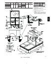
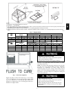
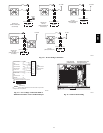
NOTES:
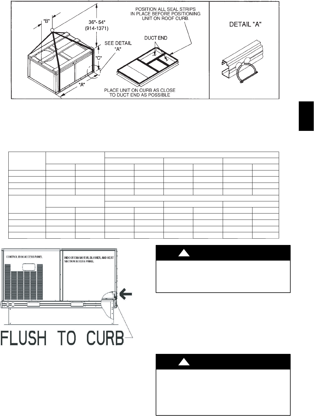
1. Place unit on c urb as close as possible to the duct end.
2. Dimensionin( )isinmillimeters.
3. Hook rigging shacklesthrough holesinbaserail asshown in detail “A.”Holesin baserailsare centered around the unitcenterof gravity.Use wooden top skid
whenriggingto prevent riggingstrapsfrom damagingunit.
4. Weights includebaseunitwithout economizer. See Table 1for unit operating weights with accessoryeconomizer.
5. Weights includebase unit withoutthe PerfectHumidityt adaptive dehumidification system. See Table 1 for unit operating weights with the Perfect Humidityt
system.
C06111
Fig. 6 --- Rigging Details
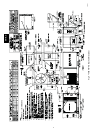
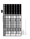
U
N
I
T
OPERATING
DIMENSIONS
UNIT
5
8
1
C
O
P
E
R
A
T
I
N
G
WEIGHT
“A” “B” “C”
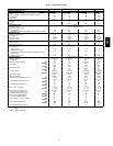
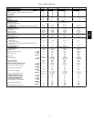
581C
lb kg in. mm in. mm in. mm
024
530 240
73.69 1872 35.50 902 33.31 847
036 540 245 73.69 1872 35.50 902 33.31 847
048 560 254 73.69 1872 35.50 902 33.31 847
060 635 288 73.69 1872 35.50 902 41.31 1050
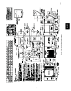
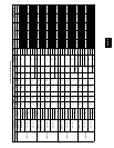
U
N
I
T
OPERATING
DIMENSIONS
UNIT
5
8
1
B
O
P
E
R
A
T
I
N
G
WEIGHT
“A” “B” “C”
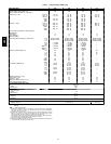
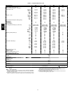
581
B
lb kg in. mm in. mm in. mm
036 530 240 73.69 1872 35.50 902 33.31 847
048 540 245 73.69 1872 35.50 902 33.31 847
060 560 254 73.69 1872 35.50 902 33.31 847
072 635 288 73.69 1872 35.50 902 41.31 1050
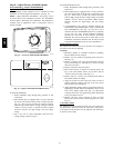
C06208
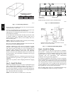
Fig. 7 --- Roof Curb Alignment
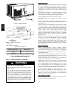
Support gas piping as shown in the table in Fig. 11. For example,
a
3
/
4
-in. gas pipe must have one field-fabricated support beam
every 8 ft. Therefore, an 18-ft long gas pipe would have a
minimum of 3 support beams, and a 48-ftlong pipe would have a
minimum of 6 support beams.
PROPERTY DAMAGE HAZARD
Failure to follow this warning could result in personal
injury, death and property damage.
All panels must be in place when rigging and lifting.
!
WARNING
See Fig. 11 for typical pipe guide and locations of external
manual gas shutoff valve.
NOTE: If accessory thru-the-bottom connections and roof curb
are used, refer to the Thru-the-Bottom Accessory Installation
Instructions for information on power wiring and gas
connection piping. The power wiring, control wiring and gas
piping can be routed through field-drilled holes in the basepan.
The basepan is specially designed and dimpled for drilling the
access connection holes.
FIRE, EXPLOSION HAZARD
Failure to follow this warning could result in personal
injury, death and/or property damage.
When connecting the gas line to the unit gas valve, the
installer MUST use a backup wrench to prevent damage
to the valve.
!
WARNING
581B,C